Hi there,
I recently bought some chips with the plan of building two or three DACs that I could tweak to my heart's content, hoping to build something (or things) that sound good, and learn something along the way if possible. I've now got this project underway, with a TDA1543 DAC which isn't working properly yet, and a PCM1793-based one, which is singing to me as I write this. This thread is about the second one.
I have cobbled this together from the circuit for the Opus USB module from Twisted Pear Audio, which feeds the DAC part of the circuit for the MiniPCM1793 DAC from HIFIDIY.net. I also used other circuits from this site for ideas on regulation and so forth. (Many thanks to those who made these circuits available).
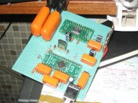
The basic setup at present is this: A PCM2707 bus-powered USB receiver is configured to give a I2S feed to the PCM1793. This is itself powered from the USB bus, through a TLV1117-33regulator for the 3.3V (digital) part, and directly for the 5V (analogue) part. I've added three ferrite thingies that I salvaged from an old VHS player to help (I hope) with noise. I am just using the R+ and L+ outputs (and GRND) through two polyester caps to remove the DC offset (something a little over a volt). I've attached a photo below.
I have several questions (some of them basic indeed), and a request for suggestions.
1. At present I have pulled the RST pin on the DAC up. (For no better reason than the DAC made no noise when I didn't...) What is this pin actually for? Should I have this wired to some kind of push switch? And if so, why?
2. I imagine I can get improved performance by using an external power supply and regulating it carefully to give a smoother 5V for the analogue part.
If I am going to go that far, I should probably use it for the 3.3V as well,
but I am less convinced about using it to self-power the PCM2707. Any opinions on how much difference these three options are likely to make? And what order of priority they should have?
3. Obviously there is a physical advantage to powering everything from the USB bus. If I stick with this idea, does anyone have suggestions on how to regulate this better?
4. I also need to decide on an output stage. Right now things already sound pretty good, and would surely sound better using the other outputs too. I am in the process of building a Pumpkin balanced preamp, which presumably can take the balanced output directly from a pair of XLRs without any other circuit. Can I tie the L- and R- outputs to ground as you (apparently) can with the Pumpkin outputs? If yes, then I will probably box it up with a couple of XLR sockets and call it a day. If no, what suggestions? (I should add, I brought the chips back from a trip abroad - getting fancy transformers or Burr-Brown opamps is difficult and pricy here in Brazil, so not all suggestions are equally practical...)
5. Is the DC offset a result of using only one half of the balanced output? Or is there something wrong I should be tracking down?
Well, thanks in advance for any help.
Cheers
Nigel
P.S. If ZenMod reads this, I haven't given up on the Pumpkin, really I haven't, it's just got a bit delayed....
I recently bought some chips with the plan of building two or three DACs that I could tweak to my heart's content, hoping to build something (or things) that sound good, and learn something along the way if possible. I've now got this project underway, with a TDA1543 DAC which isn't working properly yet, and a PCM1793-based one, which is singing to me as I write this. This thread is about the second one.
I have cobbled this together from the circuit for the Opus USB module from Twisted Pear Audio, which feeds the DAC part of the circuit for the MiniPCM1793 DAC from HIFIDIY.net. I also used other circuits from this site for ideas on regulation and so forth. (Many thanks to those who made these circuits available).
The basic setup at present is this: A PCM2707 bus-powered USB receiver is configured to give a I2S feed to the PCM1793. This is itself powered from the USB bus, through a TLV1117-33regulator for the 3.3V (digital) part, and directly for the 5V (analogue) part. I've added three ferrite thingies that I salvaged from an old VHS player to help (I hope) with noise. I am just using the R+ and L+ outputs (and GRND) through two polyester caps to remove the DC offset (something a little over a volt). I've attached a photo below.
I have several questions (some of them basic indeed), and a request for suggestions.
1. At present I have pulled the RST pin on the DAC up. (For no better reason than the DAC made no noise when I didn't...) What is this pin actually for? Should I have this wired to some kind of push switch? And if so, why?
2. I imagine I can get improved performance by using an external power supply and regulating it carefully to give a smoother 5V for the analogue part.
If I am going to go that far, I should probably use it for the 3.3V as well,
but I am less convinced about using it to self-power the PCM2707. Any opinions on how much difference these three options are likely to make? And what order of priority they should have?
3. Obviously there is a physical advantage to powering everything from the USB bus. If I stick with this idea, does anyone have suggestions on how to regulate this better?
4. I also need to decide on an output stage. Right now things already sound pretty good, and would surely sound better using the other outputs too. I am in the process of building a Pumpkin balanced preamp, which presumably can take the balanced output directly from a pair of XLRs without any other circuit. Can I tie the L- and R- outputs to ground as you (apparently) can with the Pumpkin outputs? If yes, then I will probably box it up with a couple of XLR sockets and call it a day. If no, what suggestions? (I should add, I brought the chips back from a trip abroad - getting fancy transformers or Burr-Brown opamps is difficult and pricy here in Brazil, so not all suggestions are equally practical...)
5. Is the DC offset a result of using only one half of the balanced output? Or is there something wrong I should be tracking down?
Well, thanks in advance for any help.
Cheers
Nigel
P.S. If ZenMod reads this, I haven't given up on the Pumpkin, really I haven't, it's just got a bit delayed....
Attachments
Well, at least a partial answer... I put in a 78L05 regulator fed by a wall-wart to provide cleaner voltage for the PCM1793. The analogue part is fed directly from this, the digital part from this via the TLV1117-33. So the USB is only powering the PCM2707 at the moment. This is a big improvement. I may try putting in another TLV1117-33 to self-power the PCM2707 too instead of bus-powering, although I am less convinced of the importanceof this.
Still like answers to any of the other queries above - in particular what's the "reset" pin for? I'd still like to hear suggestions for output stage too, if anyone has them.
Cheers
Nigel
Still like answers to any of the other queries above - in particular what's the "reset" pin for? I'd still like to hear suggestions for output stage too, if anyone has them.
Cheers
Nigel
Hi Nigel,
Well done on your implementation!
I just so happen to be playing around with a USB based PCM1793 DAc also and I have also implemented a PCM2707 in the past. First off my DAC is a Musiland DAC which has a Cypress EZUSB-FX2 chip doing the USB duties, an Xilinx FPGA doing the I2S, clock & other duties & feeding I2S to the PCM1793.
1. RST seem to be just that - a way to reset the DAC
2. External supply greatly improves the PCM1793 DAC - probably mostly because of the analog part is being supplied with cleaner PS? But I wouldn't discount the cleaner digital supply as being helpful also. My experience with the PCM2707 suggests it too will improve with an external PS
3. See 2 above
4. You are currently running just one half of the differential Vouts through a capacitor (to remove DC) - I plan to experiment with this & compare it to a transformer output stage that I'm posting about here http://www.diyaudio.com/forums/showthread.php?t=151568
What was there before was an OP275 opamp in balanced mode, doing Low Pass filtering & introducing about 1.8 gain to bring the output to 2Vrms.
The trafo is miles better than the op-amp. I don't know how it will compare to a cap?
There is a DC bias on the differential outputs of 1.2V (I think) so nothing wrong with your implementation - that's the DAC.
I don't know the Pumpkin preamp!
I started a thread also about the capacitor to use on the Vcom pin of the PCM1793 http://www.diyaudio.com/forums/showthread.php?t=151578 but got no replies - have you tried different caps here?
BTW, I see your fond of protboards, as I am, but I can't make out anything from your low res picture - do you have a better one?
Are you UK based or Brazil based?
Last edited:
Hi jkeny,
Thanks for the reply. It seems your DAC is a good deal more sophisticated than my attempt; these are (more or less) my first DAC (and SMD) attempts, so my idea was to try things out in a simple way first, and then have a go at things like SRC4192 reclocking and so forth later, possibly with a PCM1794 I have put aside. Things like FPGA chips are beyond me for the present.
A few follow-ups.
1. So do you have RST pulled high also? Is it worth putting a little pushbutton switch on it?
2. I think I'll have a go at self-powering the PCM2707 tonight. Now I have external power on the boards it's only another regulator, after all. The datasheet should tell me all I need to know about this, I guess.
3. Putting external power on the PCM1793 made such a difference I'm dropping the idea of fully usb-powered box for the time being.
4. I have been reading your thread about transformer coupling, and find it fascinating and would love to try it, but as far as I can find out this option is far too expensive for me to follow up here. (Heavy import taxes.) I am not satisfied with using only one half of the output - using both should give some noise-cancelling, I understand, and the capacitors I am using are cheapos (Expensive capacitors are out because of - you guessed it - heavy import taxes...). While I have nothing against opamps in principle, I am more interested in trying a discrete output stage. I found two circuits that look interesting;
http://members.quicknet.nl/ra.vdste...rs.quicknet.nl/ra.vdsteen/outputstage_en.html
and the "SACD enhancer" circuit that he links to at the bottom of the pagem which appeals to me, for some reason. Any thoughts?
Glad to hear the DC is to be expected.
If you are interested in a diy balanced preamp, there is a v. long thread describing the Pumpkin preamp (by ZenMod) on the Pass Labs forum. I've been building it, but it isn't finished yet.
I will take a look at your "capacitor on Vcom" post. I have a 1 microF polyester cap here - nothing special - and haven't experimented.
I'll try and post a larger res picture later.
I am a British expat living in Brazil - for some years now. As a whole I love life here, but sourcing parts for diy is one of the downsides...
Cheers
Nigel
Hi All,
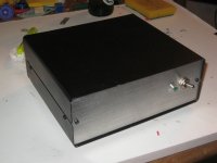
So I put another TLV1117-33 onto the board and made the alterations to self-power the PCM2707, as discussed above and recommended by jkeny. Again a noticeable improvement, although perhaps not as great a leap as putting in a separate power supply for the PCM1793. I also bought the bits and pieces to try the SACD enhancer I linked to above, and found a steel box in the junk pile at the Elec.Eng. department that I can use to box it all up. (I hate paying for chassis and boxes when there are so many that end up in landfills.)
jkeny: I took a look at your capacitor thread. I am using a 1uF polyester (bog standard) for no better reason than the schematic I dug up used one. What does your Musiland use? By the way, I guess I can't post full-res photos, but I can crop to show any bits you are particularly interested in, if you like...
Cheers
Nigel
P.S. Listening to Jessye Norman I'm wondering if maybe this really *was* as big an improvement as the previous one, after all... 🙂
I agree but then why do we DIY?Hi All,
So I put another TLV1117-33 onto the board and made the alterations to self-power the PCM2707, as discussed above and recommended by jkeny. Again a noticeable improvement, although perhaps not as great a leap as putting in a separate power supply for the PCM1793. I also bought the bits and pieces to try the SACD enhancer I linked to above, and found a steel box in the junk pile at the Elec.Eng. department that I can use to box it all up. (I hate paying for chassis and boxes when there are so many that end up in landfills.)
Musiland uses 2 uF MKT - I tried electros, film caps, electro & film cap.jkeny: I took a look at your capacitor thread. I am using a 1uF polyester (bog standard) for no better reason than the schematic I dug up used one. What does your Musiland use?
no particularBy the way, I guess I can't post full-res photos, but I can crop to show any bits you are particularly interested in, if you like...
sections - just need a higher res all round!
P.S. Listening to Jessye Norman I'm wondering if maybe this really *was* as big an improvement as the previous one, after all... 🙂[/QUOTE]
I agree but then why do we DIY?
Well, it's still diy, of course, and often a lot of it... If I am going to make something for the living room (which therefore needs approval from my wife) then I try to design something nice, spend a little money and build from scratch, but if it's something experimental I'd rather spend the time on the electronics and save some cash by recycling something. And, of course, a used box still requires a good deal of work to get it looking reasonable.... a different sort of diy challenge, I guess.
I think I might try fiddling with the Vcom cap. Probably better to get the output stage done first, though. I'd still be interested to hear if you have any thoughts on that discrete output stage.
Cheers
Nigel

Well, it's still diy, of course, and often a lot of it... If I am going to make something for the living room (which therefore needs approval from my wife) then I try to design something nice, spend a little money and build from scratch, but if it's something experimental I'd rather spend the time on the electronics and save some cash by recycling something. And, of course, a used box still requires a good deal of work to get it looking reasonable.... a different sort of diy challenge, I guess.
I agree, this is the most difficult part for me - making it all wife friendly - consumes al lot of my time!
The jury is still out on the Vcom cap as I don't have a high capacitance film to try but as I said in the other thread it seems to behave like a signal passing cap - high capacitance needed for bass response but film cap need for crystalline highs. This is what I hear but I need confirmation from others as the effect is slight - I hope it's not more psycho then acoustics that I'm experiencing 🙂
jkeny: I have a few caps in my parts box that look like MKT caps to me. (plastic boxes, right?) I have a coupl of 1uF, and a 3.3uF. I don't think it would be too tough to stick one of these in and see what difference it makes, so I'll give it a go. However, these are pretty old (and used!) so any results should be taken with a pinch of salt. Since I don't have any really high-quality film caps I can't help there, but I' love to hear about any experiences.
I also feel I need a better output stage first - just pushing everything through the cheap film caps I have at the end may mask any improvement anyhow... Did you have a chance to take a look at the circuit I linked to?
I am attaching it below. (I hope noone minds my doing this, but I can't get a direct link to work, and in any event, I think all appropriate copyright info is there.) Any thoughts on this circuit?
Cheers
Nigel
Attachments
An update...
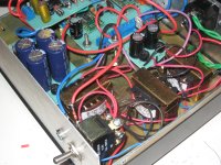
I decided to go ahead and build the "SACD enhancer" output stage I linked to above, and finish off the DAC. I put the output stage on a separate board, so it can be switched out without too much trouble if I feel like it. Three power supplies - one transformer/bridge rectifier combo feeds separate 3.3v regulators for the PCM2707 and the digital part of the PCM1793, another feeds a 5v regulator for the analogue side of the PCM1793, and a third runs a separate PSU for the output stage.
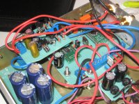
I made a couple of alterations due to the parts I had on hand - the output caps are two 22uF bipolars I had lying around, and I decided to put a couple of old 4n7 paper-in-oil capacitors in parallel with them, to see what would happen. (These appear to be really old, but have never been soldered, and don't appear to have leaked,so I'm guessing they're OK. I'm also translating "a oleo" as "paper-in-oil", but for all I know it's something-else-in-oil).
Since I don't have a distortion analyser (hell, I don't even have an o-scope...) I can only use my ears to minimise distortion by adjusting the trimpot. I already have it sounding *much* better than the temporary setup I had going before, and with a little effrot I can probably tweak it a little more. We'll see.
jkeny: If using a cap on only half of the balanced output gives you good results please post - I'd like to compare experiences. I'm only sorry I can't get hold of transformers to try out, but the circuit I used is dead simple, and I think it's worth your time and effort to give it a try. (I made no attempt to match transistors - anyone think it would make a difference here?)
All comments welcome, as always. Long-term plan is to use this experience in planning and building another DAC based on a PCM1794, this time with optical input as well as USB, so please poast any and all suggestions.
Cheers
Nigel
I decided to go ahead and build the "SACD enhancer" output stage I linked to above, and finish off the DAC. I put the output stage on a separate board, so it can be switched out without too much trouble if I feel like it. Three power supplies - one transformer/bridge rectifier combo feeds separate 3.3v regulators for the PCM2707 and the digital part of the PCM1793, another feeds a 5v regulator for the analogue side of the PCM1793, and a third runs a separate PSU for the output stage.
I made a couple of alterations due to the parts I had on hand - the output caps are two 22uF bipolars I had lying around, and I decided to put a couple of old 4n7 paper-in-oil capacitors in parallel with them, to see what would happen. (These appear to be really old, but have never been soldered, and don't appear to have leaked,so I'm guessing they're OK. I'm also translating "a oleo" as "paper-in-oil", but for all I know it's something-else-in-oil).
Since I don't have a distortion analyser (hell, I don't even have an o-scope...) I can only use my ears to minimise distortion by adjusting the trimpot. I already have it sounding *much* better than the temporary setup I had going before, and with a little effrot I can probably tweak it a little more. We'll see.
jkeny: If using a cap on only half of the balanced output gives you good results please post - I'd like to compare experiences. I'm only sorry I can't get hold of transformers to try out, but the circuit I used is dead simple, and I think it's worth your time and effort to give it a try. (I made no attempt to match transistors - anyone think it would make a difference here?)
All comments welcome, as always. Long-term plan is to use this experience in planning and building another DAC based on a PCM1794, this time with optical input as well as USB, so please poast any and all suggestions.
Cheers
Nigel
Attachments
Hi Nigel,
Good work, looks neat. You've really gone high res on the pics now - can even see your fingerprint on the white table 🙂
You like the SACD enhancer better than the cap output? I'll go back to listening to cap output on one differential leg when I get a chance & give you my impressions - I've just so many variables to nail down here at the moment -remind me if I forget 😉
Hi Nigel,
Good work, looks neat. You've really gone high res on the pics now - can even see your fingerprint on the white table 🙂
You like the SACD enhancer better than the cap output? I'll go back to listening to cap output on one differential leg when I get a chance & give you my impressions - I've just so many variables to nail down here at the moment -remind me if I forget 😉
I definitely like this SACD enhancer *much* better than the cap output. Having said that, I don't have access to big audiophile-quality caps, or indeed anything other than completely standard stuff, so I'd be interested to hear what you hear when you find the time to try it.
Let me repeat my suggestion to give this SACD enhancer a try. I'd also like to hear from anyone who tried the jfet circuit I linked to above.
Glad the resolution is better. It seems I should be able to post larger still - let me know if these aren't sufficient.
Cheers
Nigel
I definitely like this SACD enhancer *much* better than the cap output. Nigel
In what ways can you say it's better - detail, presence, dynamics, etc?
More dynamic range, yes, and more detail. I'm not quite sure what you mean by "presence", but let me guess that you mean a heightened sense that the sound could conceivably be real (or "live") rather than a recording. (Perhaps we could say that we can "suspend disbelief" more easily.) If that's what you mean then yes, that is the principal difference.
Actually, this is what we're all looking for, isn't it? I care much more about this than noise levels and so forth, although I am willing to believe that these more "quantifiable" factors contribute greatly to this "suspension of disbelief", and I wouldn't be surprised if people with better measuring equipment and more experience than I have could show this to be the case.
As things are, however, subjective opinions are all I have... 🙂
Cheers
Nigel
- Status
- Not open for further replies.
- Home
- Source & Line
- Digital Line Level
- A few questions on a PCM1793-based USB DAC