Good grief, who designed that thing? I don't doubt it did work acceptably but the component selection and circuit impedances are way off-beam for solid state. Modern equivalents for the small signal transistors would be BC548 or similar for BC108, though with that huge 13M volume pot and 1M balance pot, adding a ground connection to the metal case of the first stage transistors might be a wise precaution.
Also, you can bet it's unstable and noisy without its original PCB, if there ever was one. I certainly wouldn't waste time with a breadboard assembly either, if that's what you're planning for test purposes.
Also, you can bet it's unstable and noisy without its original PCB, if there ever was one. I certainly wouldn't waste time with a breadboard assembly either, if that's what you're planning for test purposes.
@OldDIY
You must have a different datasheet to mine. In the Mullard 1974 databook it says 1W dissipation. I doubt a 225mW limit would have been useful in output stages. Also 2A output (pulsed only, though), so would be OK at 1A.
In a class AB circuit the "off" state transistor is allowed to operate at Vcer (or even Vcex). Vcer=18V for AC187/8. With simple single O/P pair, one is reverse biased by the other" transistor. Not always the case if driver transistors are used as with a quasi-complementary circuit. In principle, you could make a 4W amplifier with these for 8 ohms at 18V supply. I'd certainly re-emphasise using the standard 4 transistor approach and test it at 9V first though. This design was obviously (as Ian indicated) designed in very early days when transistors were expensive and you had to get as much value out of each as possible. Not that that excuses some of the "features" in this circuit!
But- on second thoughts, reading the datasheet again, they are only rated for 3W output. Keep the supply to 9-15V after all!
p.s. I would also use a Baxandall type tone control circuit, not the passive sort shown which is inherited from valve circuits. They really needed an antilog pot, not a linear. That would mean setting the "flat" response somewhere near one end and make the cut/boost scale look lopsided.
Last edited:
My old TD Towers says AC187K is 2A and 1 watt if mounted on a heatsink.
The AC188K is similar. None K version shown as a different manufacturer and 225mW dissipation in free air.
I used to have a Grundig Signal 500E (all from memory) that I think used these and it had a cracking subjective sound quality and had no trouble driving a home made 3 way speaker system using an Elac 10" main driver.
This is Grundig but not the Signal 500E although it looks very similar from memory. This uses a PNP driver rather than NPN and no emitter resistors. That could get interesting...
Attachments
Wow thank you JMFahey that was really helpful.
Yes I do want to actually build it. I have been putting it off for way too long (couple of years) and it seems like an interesting project. Would be great if I could build it on a perfboard because I don't want to order the circuit boards and than find out that the layout is messed up...
I tried building a few little chip amps before and i always get oscillation and noise... Probably bad layout.
Anyways thanks for the help so far.
The Mullard book shows that the device has to have a heatsink for 1W operation. The K version (/01 in the book rather than K) is preferred as that has an attached square section casing with a mounting hole for good thermal contact. Bigger heatsink needed for the plain TO-1 case.
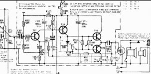
Mooly- your Grundig circuit is very much like the standard 4 transistor design I had in mind, but I would not use the cheap trick of connecting the bootstrap to the output as I would avoid D.C. in the speaker, plus risk of upsetting if the speaker is unplugged. Worked in radios with hardwired speakers. Using a separate bootstrap cap means you can use NPN or PNP driver. An NPN always seemed to be better in the old days, but with modern complements almost identical not much to choose these days.
One of those resistors in the bias circuit might be a thermistor. Mullard circuits looked similar - no emitter resistors when a thermistor was used. I'd still use emitter resistors though.
Probably, though, if building a 3W (to 4W, if brave) circuit a higher power driver might be preferable just to run cooler. If TO-39 available like 2N3019 that would be a good choice but possibly overkill. Or a BD139.
Some of those old radios did seem to produce good quality sound and if I get a chance to repair a couple of old 60's sets I'm sure they would still sound better than my PC with "tinny" internal speakers.
Here is a one more interesting circuit.
You like the typical Germanium sound from the 1970's? (2W Audio amp. with 2 Germ. end transistors)) - YouTube
It doesn't have a tone controls but it is simple.
You like the typical Germanium sound from the 1970's? (2W Audio amp. with 2 Germ. end transistors)) - YouTube
It doesn't have a tone controls but it is simple.
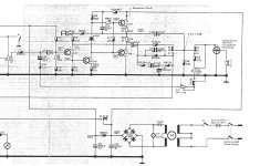
The schematic at post #1 does not seems to be the best one to start. To recreate a circuit, the schematic shoud not have proprietary or hard to find parts such as thermistors; voltages and bias currents should be clearly specified. You will find about a thousand schematics with the AC187/AC188 transistor pair at the radiomuseum.org web site. Search the AC187 transistor. Scroll down to the "usage in models" section and click on a year. This transistor has been popular in 1968 and 1969, so I browsed trough that years results. Tape players often have a better audio section, so I searched for a reputable tape player manufacturer. The Uher 714 tape player schematic seems to be a good candidate, but there could be even better ones. The switches on the schematic are in the play position; components excluded by switches are for the record funcion, and should be omitted. I guess you may also search for AC180/AC181 transistors, they are like AC187/AC188 with better specifications.
Attachments
What do you think about the circuit that I found on YouTube.
You like the typical Germanium sound from the 1970's? (2W Audio amp. with 2 Germ. end transistors)) - YouTube
Its wold be easier to build since the video explains it pretty well.
You like the typical Germanium sound from the 1970's? (2W Audio amp. with 2 Germ. end transistors)) - YouTube
Its wold be easier to build since the video explains it pretty well.
They are all variations of the same theme. That one has the speaker in the driver stage current path... you were saying...
It's all very cost effective 🙂
It's all very cost effective 🙂
Mooly- your Grundig circuit is very much like the standard 4 transistor design I had in mind, but I would not use the cheap trick of connecting the bootstrap to the output as I would avoid D.C. in the speaker, plus risk of upsetting if the speaker is unplugged. Worked in radios with hardwired speakers. Using a separate bootstrap cap means you can use NPN or PNP driver. An NPN always seemed to be better in the old days, but with modern complements almost identical not much to choose these days.
Attachments
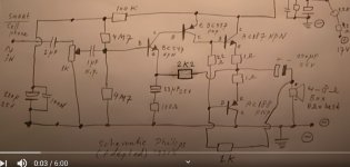

that screenshot leaves a lot to be desired. 4.7M input resistors with a 1k input pot? No base resistor on the PNP driver ... 1k bootstrap resistor not enough drive current? especially for 4 ohm load. tiny output caps at 220uF. Might suit "tranny radio"with speakers that could not manage 100Hz, but does not do justice to the AC187/AC188.
The first amp I ever built was a kit (which was germanium outputs using AD149's) and that used 470uF speaker coupling caps... and it was GREAT 😀
It sounded every bit as good as the B&O system my parents had when played through the B&O speakers.
It sounded every bit as good as the B&O system my parents had when played through the B&O speakers.
I found a circuit diagram for grundig signal 500 and also found this on this website... Diagram doesn't have component values but they are listed in the parts list...
3W Audio Amplifier Using AC187-AC188 Pair - Engineering Projects
This seem simple and has 500uf output cap only problem is T2 (Bc158) it is quite expensive. Could these small transistors be replaced with something newer and available?
3W Audio Amplifier Using AC187-AC188 Pair - Engineering Projects
This seem simple and has 500uf output cap only problem is T2 (Bc158) it is quite expensive. Could these small transistors be replaced with something newer and available?
BC158's were ten a penny general purpose PNP's in the old 'lockfit' triangular package.
Any small high gain signal PNP type would be fine.
Any small high gain signal PNP type would be fine.
You can find another schematic with AC187 K | AC188 K transistors 3.6Watts amplifier
in this post Germanium investigations 🙂
in this post Germanium investigations 🙂
Thanks
I will probably try that 3w circuit because it has only 5 capacitors, some resistors and doesn't need thermistor or diode.
I don't really want to spend a ton of money because I plan on putting together much better setup soon. This is just for my 1960s vintage speakers that are around 3-5w but sound really nice.


 Thermistor protect Ge transistors against thermal runaway
 - Home
- Amplifiers
- Solid State
- A few questions about re creating vintage amplifier using ac187/188 K germanium pairs