MikeB,
Your point about stability is good... and again this comes back to having a good forward function in the first place... with the dominant pole far above the desired the desired closed loop response.
As far as the FM is concerned... it is caused by the feedback... and because the frequency shift is small.... it does not show up in FFT or spectral analysis.
😉
john curl said:Feedback also causes FM distortion. Get out of that one, if you can!😀
nothing to be "gotten out of" has ever been put forth by you and other pim distortion advocates - where is the test data showing people can pick out 90 degree phase shifted distortion products that are 100X lower than than your preferred AM distortion products?
"AM" vs "FM" modulation products:
http://www.diyaudio.com/forums/showthread.php?postid=485573#post485573
here you admit to only having an intuition:
http://www.diyaudio.com/forums/showthread.php?postid=485857#post485857
but I've repeatedly pointed out that PIM is represented by distortion products whose amplitudes decrease with higher loop gain - Otla's math "hides" the loop gain term but it is there if you work through it
simulation shows high loop gain reducing distortion - "AM" and "PM" alike
http://www.diyaudio.com/forums/showthread.php?postid=489927#post489927
how quickly we forget - things that don't fit our pet theories
Get 'em JCX.... get 'em...
The FM modulants pretty much peter away when the forward function is clean enough...
😉
The FM modulants pretty much peter away when the forward function is clean enough...
😉
Hi, MikeB,
But in my experiments, loading the VAS with R or C to ground (for stability, ie:not using miller cap) seems to give better sonics.
MikeB, there are another 2 R positions that to my experience does gives better sonics. In your sims, what are they doing to OL performance?
The first one is this one : R about 220k (215k in this example) in the position of miller cap. In here it is // with 15pf miller cap. In Doug Self book, it is said to flatten the OL curve, extending the OL bandwith. Is this true in your sims?
Thanks alot 😀This shows the naked face of nfb...
OKNo phasehifts/delays, only plain gains and feedbacks. This shows the naked face of nfb... This circuit gives openloop a nice and plain 2nd harmonic.
OKObserve that the nfb added high order harmonics that are not existant in the OL-dist.
OK. This answers my own questions about things in DougSelf book. He said that stabilizing or loading the VAS is in any point of view sub optimal than putting millercap, for example (in stabilizing). Simple words = "Do not load the VAS"This does not only apply to global nfb, local feedbacks have the same problem. This means, a single miller cap can create high order harmonics for higher freqs.
But in my experiments, loading the VAS with R or C to ground (for stability, ie:not using miller cap) seems to give better sonics.
simple r-loads to the vas do a great job, they reduce distortions without local feedback AND flatten out the OL-bandwidth
MikeB, there are another 2 R positions that to my experience does gives better sonics. In your sims, what are they doing to OL performance?
The first one is this one : R about 220k (215k in this example) in the position of miller cap. In here it is // with 15pf miller cap. In Doug Self book, it is said to flatten the OL curve, extending the OL bandwith. Is this true in your sims?
Attachments
The second one is this one.
If in your Symasim, you put R from VAS to ground (upper and lower of VBE multiplier).
What these 4k7 (also upper and lower of VBE multiplier, connected to output node, not to ground like your Symasim) do? To my hearing they give better sonics too, but what actually they do to OL performance?
If in your Symasim, you put R from VAS to ground (upper and lower of VBE multiplier).
What these 4k7 (also upper and lower of VBE multiplier, connected to output node, not to ground like your Symasim) do? To my hearing they give better sonics too, but what actually they do to OL performance?
Attachments

Regarding FM distortion, what does Barrie Gilbert say about it? Does he 'hide' what "really" happens as well?
Greetings from Norfolk
For the newcomers could you show a bit more of the circuit you gave a portion of, I am not familiar with the Dymasim and would like to know more.
ALSO - refering back to your other mail.
In the case where you put a resistor in parallel with a small capacitor (215K // 15 pF) it must be assumed that the resistor, enen with the parallel capacitor reduced the effective time constant of the of the collector base 'circuit' as well as defining and reducing the transistors gain.
Again a full circuit would help, not being familiar with your reference
Richard
lumanauw said:The second one is this one.
If in your Symasim, you put R from VAS to ground (upper and lower of VBE multiplier).
What these 4k7 (also upper and lower of VBE multiplier, connected to output node, not to ground like your Symasim) do? To my hearing they give better sonics too, but what actually they do to OL performance?
For the newcomers could you show a bit more of the circuit you gave a portion of, I am not familiar with the Dymasim and would like to know more.
ALSO - refering back to your other mail.
In the case where you put a resistor in parallel with a small capacitor (215K // 15 pF) it must be assumed that the resistor, enen with the parallel capacitor reduced the effective time constant of the of the collector base 'circuit' as well as defining and reducing the transistors gain.
Again a full circuit would help, not being familiar with your reference
Richard
Hi Lumanauw !
I have not read all D.Self articles, but obviously he was not aware of the high order nature of nfb...
Of course this 220k resistor does flatten OL-bandwidth, it's a pure local nfb !
By R/C loading the vas you reduce Z-out of vas, making it less sensitive to the reactive loads from vas, greatly reducing dynamic phasehifts, you linearize it and flatten old-bandwidth. "Do not load the VAS", Self is funny, the outputstage is the worst load to the vas imaginable ! R-loading the vas is bad if you're looking for ultra low THD at 1khz and not for good sonics. 😉
About your 2nd circuit, these resistors will not linearize, but they boost gain by applying positive feedback. The vas will have lower zout, making it less sensible to the wild load from the outputstage, but it's very likely to reduce the amps ability to drive complex loads. This amp will seize to work good without GNFB.
John Curl, about FM distortion. FM is known to create plenty of harmonics, that's why it is used for FM-synthesis, it's the easiest way to create a tone with tons of harmonics. 😉 With only 3 operators you are already able to create a tone beeing quite similar to a sax.
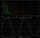
I did some FFT on FMs, see attached results. The red one looks perfectly like a tanh() distortion from a diffamp, (funny that it can be represented by a simple FM), the green one represents a dynamic phasehift caused by asymetric slewrate. It's very obvious that this kind of distortion is ABSOLUTELY EVIL, it creates sub harmonics. High gain ccs'd vas tend to do that. A balanced push/pull vas not. Also, this distortion will be rising with frequency.
But, these are all defects not beeing in any relation to nfb. It's true that a constant phasehift between freqs will not show up in FFT (harmonics), but only if they are constant. The moment these phasehifts are varying you get FM, causing harmonics. NFB will mostly compensate those phasehifts as they create an error voltage. (Okay, partial compensation of dynamic phasehifts might be a problem)
I will try to simulate dynamic phasehifts within a closed loop, but this it getting difficult with virtual devices...
An openloop amplifier will show the same defects about dynamic phasehifts, but likely smaller because of the low gain.
I believe that distortions not creating harmonics are a fairy tale, and even if they exist, how should you be able to hear them ? Principally you do hear with an fft... Of course exact reproduction of phasehifts is necessary for the soundstage.
Mike
I have not read all D.Self articles, but obviously he was not aware of the high order nature of nfb...
Of course this 220k resistor does flatten OL-bandwidth, it's a pure local nfb !
By R/C loading the vas you reduce Z-out of vas, making it less sensitive to the reactive loads from vas, greatly reducing dynamic phasehifts, you linearize it and flatten old-bandwidth. "Do not load the VAS", Self is funny, the outputstage is the worst load to the vas imaginable ! R-loading the vas is bad if you're looking for ultra low THD at 1khz and not for good sonics. 😉
About your 2nd circuit, these resistors will not linearize, but they boost gain by applying positive feedback. The vas will have lower zout, making it less sensible to the wild load from the outputstage, but it's very likely to reduce the amps ability to drive complex loads. This amp will seize to work good without GNFB.
John Curl, about FM distortion. FM is known to create plenty of harmonics, that's why it is used for FM-synthesis, it's the easiest way to create a tone with tons of harmonics. 😉 With only 3 operators you are already able to create a tone beeing quite similar to a sax.
I did some FFT on FMs, see attached results. The red one looks perfectly like a tanh() distortion from a diffamp, (funny that it can be represented by a simple FM), the green one represents a dynamic phasehift caused by asymetric slewrate. It's very obvious that this kind of distortion is ABSOLUTELY EVIL, it creates sub harmonics. High gain ccs'd vas tend to do that. A balanced push/pull vas not. Also, this distortion will be rising with frequency.
But, these are all defects not beeing in any relation to nfb. It's true that a constant phasehift between freqs will not show up in FFT (harmonics), but only if they are constant. The moment these phasehifts are varying you get FM, causing harmonics. NFB will mostly compensate those phasehifts as they create an error voltage. (Okay, partial compensation of dynamic phasehifts might be a problem)
I will try to simulate dynamic phasehifts within a closed loop, but this it getting difficult with virtual devices...
An openloop amplifier will show the same defects about dynamic phasehifts, but likely smaller because of the low gain.
I believe that distortions not creating harmonics are a fairy tale, and even if they exist, how should you be able to hear them ? Principally you do hear with an fft... Of course exact reproduction of phasehifts is necessary for the soundstage.
Mike
Attachments

Hi MikeB,
All people here talk about Slewrate in terms of Voltage, In my opinion Slewrate in terms of Current is also a contributing factor in terms of HF SoniX
K a n w a r
All people here talk about Slewrate in terms of Voltage, In my opinion Slewrate in terms of Current is also a contributing factor in terms of HF SoniX
K a n w a r
Hi, Gandalph,
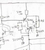
The first one, look at my handdrawing in post #37. It has 4 differential (high OL / high feedback design), the first one(s) is K389-J106 Jfet complementary differential (so it can receive high input voltage - Otala paper), the second one(s) is MAT03/04 (matched transistors), VAS is made by high HFE BC550/560, cascoded by LED drop (to reduce distortion caused by voltage swing in VAS / Early effect), linearized by 220K//15pf, and loaded by 21k5 to ground (like MikeB's Symasim (not Dymasim)😀 )
The second one comes from NP's Statis2-3 schematic, you can search for it in here somewhere.
MikeB, I went through 'Are OP Amps Really Linear?' by Barrie Gilbert who knows his stuff. If you can explain to me where he went wrong when he stated, after much math, that: "Then, the actual phase angle is 6.01 degrees. By E=5, it has increased to 9.14 degrees. This is not what we would expect from a LINEAR amplifier, whose phase should quite independent of amplitude. In certain applications, this excess phase and its variation with signal level will be very troublesome. " Page 6 of 7
In other words, we have a dynamic phase shift that changes with output voltage level, of audio frequencies. I don't find any way that adding feedback fixes this problem.
In other words, we have a dynamic phase shift that changes with output voltage level, of audio frequencies. I don't find any way that adding feedback fixes this problem.
Hi John !
Yes, such behaviour is frightening... Are we talking of dynamic phaseshifts, immediately applied by the current level of outputvoltage (which occurs through the nature of bjt, changing capacitance with Vce) means FM distortion, or a permanent phaseshift dependent on the amplitude of the signal, means no distorted signal ? The 2nd gets difficult to imagine where to come from, maybe local heatup ?
Whatever, ANY phasehift will create an errorvoltage visible to the feedback and will be reduced.
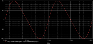
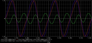
I attached the first case, FM distortion by dynamic phaseshift, Blue = original signal, Red = FM-distorted signal by level dependent phaseshift, Green = error voltage as seen by the feedback.
One bigger problem that occurs with nfb is the reactive input of the bjt on the -input of the diffamp, this will create new phasehifts. In worst case it will create dynamic phaseshifts out of control of nfb. Thats where CFB is superior...
Another problem: A phaseshift of only 10° already creates an error voltage with up to 17.5%, driving the nfb quite busy. Gladly, in this case nfb does not add distortions yet. But, with a dynamic phasehift it does, as the FM distortion is a distortion. But these fall under open loop distortion and will be immediately visible with fft.
My point is, if an amp makes an error, the outputvoltage will be different to the inputvoltage and create an error voltage. If input and output voltage are identical (except the amplitude) the amp has made no error. There can't be any distortion mechanism not creating an error voltage.
The question is only how effective this error voltage can be used to compensate the made errors.
And, amplifiers tend to distort the inputsignal...
Lumanauw ! It's "Symasym"... I need a new name, i've seen at least 20 variations now...
Mike
Yes, such behaviour is frightening... Are we talking of dynamic phaseshifts, immediately applied by the current level of outputvoltage (which occurs through the nature of bjt, changing capacitance with Vce) means FM distortion, or a permanent phaseshift dependent on the amplitude of the signal, means no distorted signal ? The 2nd gets difficult to imagine where to come from, maybe local heatup ?
Whatever, ANY phasehift will create an errorvoltage visible to the feedback and will be reduced.
I attached the first case, FM distortion by dynamic phaseshift, Blue = original signal, Red = FM-distorted signal by level dependent phaseshift, Green = error voltage as seen by the feedback.
One bigger problem that occurs with nfb is the reactive input of the bjt on the -input of the diffamp, this will create new phasehifts. In worst case it will create dynamic phaseshifts out of control of nfb. Thats where CFB is superior...
Another problem: A phaseshift of only 10° already creates an error voltage with up to 17.5%, driving the nfb quite busy. Gladly, in this case nfb does not add distortions yet. But, with a dynamic phasehift it does, as the FM distortion is a distortion. But these fall under open loop distortion and will be immediately visible with fft.
My point is, if an amp makes an error, the outputvoltage will be different to the inputvoltage and create an error voltage. If input and output voltage are identical (except the amplitude) the amp has made no error. There can't be any distortion mechanism not creating an error voltage.
The question is only how effective this error voltage can be used to compensate the made errors.
And, amplifiers tend to distort the inputsignal...
Lumanauw ! It's "Symasym"...
I need a new name, i've seen at least 20 variations now...Mike
Attachments
I don't think so. Please read Barrie Gilbert's analysis, before coming to any conclusion. If feedback could fix it, then Barrie Gilbert would not write about it. There is no proportional term regarding the amount of feedback in his final equation.
john curl said:I don't think so. Please read Barrie Gilbert's analysis, before coming to any conclusion. If feedback could fix it, then Barrie Gilbert would not write about it. There is no proportional term regarding the amount of feedback in his final equation.
John,
Are you referring to the equation for HD3 at the end of the article, or the Vin equation just before that one? (Barrie should have numbered the equations!).
Jan Didden
http://web.archive.org/web/20010821120135/http://www.edtn.com/analog/barrie4.htm
Fine article, but you are still just seeing what you want in the analysis and ignoring the relevance of Gilbert's assumptions, which he himself points out:
"Formally, this input cell is a nonlinear transconductance"
for negative feedback to work an absolute requirement is a Linear difference measurement, in the real world we have to live with some nonlinearity but we cannot expect negative feedback to work when we force operating conditions that give significant nonlinear products in the input differential stage
"It must be again noted that this is for operation at w1/100, and a gain of ten;"
linearization from negative feedback also requires sufficient excess gain - Gilbert is analyzing a loop with only 20 dB loop gain - feedback error series math has been done repeatedly with results you should well know: that negative feedback does create "new" harmonics in the output, that there is a "hump" in the relative levels of the harmonics which moves to higher harmonics as the feedback factor is increased and that higher negative feedback reduces the levels of all of the error harmonics; low negative feedback IS worse than higher negative feedback, sufficiently high loop gain can push all of the error harmonics into the noise floor over the bandwidth you can obtain high loop gain
"Modern op amps -- even ones of this unity-gain frequency -- are, of course, far better than this. One reason is the use of a modified input (gm) stage having the capacity to cope with a large open-loop error signal."
Glibert points to linearizing the input but ignores a powerful linearizing technique: more loop gain - with more loop gain the signal at the input is reduced proportionately and the distortion to linear error signal ratio in the difference improves by the square of the gain (for for undegenerated the bjt pair assumed here)
of course another linearizing technique is to use local negative feedback (still more gain in the loop just not all of it visible as global loop gain):
http://www.diyaudio.com/forums/showthread.php?postid=501789#post501789
There are circuits that have inborn linearity and don't suffer from transistor's weaknesses like Miller effect, Early effect, beta nonlinearity. Current driven common base with high referance voltage and low impedance at base is one of them, another is wilson's mirror and most usefull- emitter follower.
With them one does not really need to think of dynamic phase shifts and choose models extramely carefully.
So why not omit the ubiquotous common emitter whose any value/parameter is dependent on all others and vice versa and build amplifiers with more linear circuits?
best ragards to all
With them one does not really need to think of dynamic phase shifts and choose models extramely carefully.
So why not omit the ubiquotous common emitter whose any value/parameter is dependent on all others and vice versa and build amplifiers with more linear circuits?
best ragards to all
It is important here to note that we have a problem of DYNAMIC phase shift that will be within the audio band. Now, can we use 'more linear' op amp input stages? Yes. Can we use 'less linear' op amp input stages? Yes.
Barrie's analysis presumes a perfect preamp, except for the input stage. The input stage is an ideal differential transistor pair. How typical of the 5532 op amp and many IC power amps, etc, etc. He sets the op amp for a gain of 10. Is this too much? Seems conservative to me.
IF you knew Barrie, like I know Barrie, he would not bother with this, unless it was seen by him as a problem. 32 yeas ago, when I tried to explain TIM to him, at a conference, you should have seen his face. I appeared to be pretty 'far out', to the point annoyance to him. Actually, today, he has a good understanding of TIM, but then it took a number of years before he realized what I was trying to point out, back in 1974.
Now, he is the 'champion' of PIM! Only 15 years after Matti Otala first wrote a 'qualitative' analysis of the problem (equations), that was not put into the 'AES Journal' because someone objected to it. And so it goes.🙂
MikeB said:About the high order harmonics generated by nfb...
Some interesting tests about the effects of nfb can be done in sims with a virtual amp. No phasehifts/delays, only plain gains and feedbacks. This shows the naked face of nfb... This circuit gives openloop a nice and plain 2nd harmonic.
The simulationresults are: (outputvoltage 1v)
Green: OL-gain of 1000, OL-distortion 10%
Red: OL-gain of 100, OL-distortion 1%
Blue: OL-gain of 1000, OL-distortion 1%
Yellow: OL-gain of 32000, OL-distortion 1%
Observe that the nfb added high order harmonics that are not existant in the OL-dist.
The degree of the harmonics falling with frequency seem to be set by openloop distortion.
This shows just one thing: no matter if no feedback, low feedback or high feedback, OL-distortion must be kept at a minimum. (not a surprise)
This does not only apply to global nfb, local feedbacks have the same problem. This means, a single miller cap can create high order harmonics for higher freqs.
Unity gain feedback shows the same symptoms.
Lumanauw, to your question, simple r-loads to the vas do a great job, they reduce distortions without local feedback AND flatten out the OL-bandwidth. They simply reduce distortions the same amount they reduce gain, at first sight this does not make sense, but through the nature of nfb it does reduce high order harmonics.
Symasym for example has <1% OL-distortion (checked with 3V 20khz into 4 ohms) and 89db OL-gain.
With low enough OL-distortion and high feedback the high order harmonics created by nfb will be below noise.
Observe the yellow distortion, the first high order harmonic created by nfb is already at -140db, below a typical noisefloor of -120db. Here, the negative effects from nfb become negligible.
These attached result shows, that if nfb is misused, it does VERY bad things.
This is no mystique voodoo, just plain physics/math.
The real problem with nfb is stability.
Mike
Hello Mike,
please can You explain what is inside the "box"?
I would think in Your schematic isn´t any non linearity!
When it´s so, it cannot generate any distortion.😕
May be that the simulator do some?😉
Regards
Heinz!
- Status
- Not open for further replies.
- Home
- Amplifiers
- Solid State
- A few naive questions