hi pal
thanks 🙂
once i get 2 diodes i will follow your bi-phrase circuit and try again
🙂
one more question about it
tho
if i connect 9 and 9 to get 18*1.414
will the max current output be still 1.1A since like andrew T said
the MAX current output would be this value?
thanks
regards
thanks 🙂
once i get 2 diodes i will follow your bi-phrase circuit and try again
🙂
one more question about it
tho
if i connect 9 and 9 to get 18*1.414
will the max current output be still 1.1A since like andrew T said
the MAX current output would be this value?
thanks
regards
Yes this is the max output, (the 20VA rating) .
Bi-Phase wiring allows this at 9v and 2 A (1 amp from each half of the wiring at the lower voltage ) the power available will be the same.
At least that is my understanding.
Bi-Phase wiring allows this at 9v and 2 A (1 amp from each half of the wiring at the lower voltage ) the power available will be the same.
At least that is my understanding.
WHY WILL IT TURN ON WHEN I CLAP AND TURN OFF A SHORT TIME AFTERWARDS?
hi, im new to this website.
im 16 years old and have been trying to complete this circuit for a long long time and finally tonight ive completed it.
after completing it i messed round with it for a while trying different outputs eg, motors, buzzers and all worked fine.
i can clap to turn it on and clap again to turn it off.
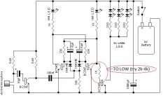
i experimented for a bit with resistors, taking them out, adding them, and found that the reason my circuit would turn on when i clap and turn off again a short time after is because the 1k resistor connected to the base of one transistor, collector of one transistor and the LED with a 1k limiting resistor was becaue the 1k resistor was too low so i changed the resistor to a 2k-4k and found that it would stay on.
i hoped that you understood what i was trying to say, and that it helped.
i have a feeling that this wont work for some people.
if you have any questions about what i have talked about feel free to email me at i_hate_skool_2@hotmail.com.
ive added a schematic to highlight what i was trying to put in words so take a look.
hi, im new to this website.
im 16 years old and have been trying to complete this circuit for a long long time and finally tonight ive completed it.
after completing it i messed round with it for a while trying different outputs eg, motors, buzzers and all worked fine.
i can clap to turn it on and clap again to turn it off.
i experimented for a bit with resistors, taking them out, adding them, and found that the reason my circuit would turn on when i clap and turn off again a short time after is because the 1k resistor connected to the base of one transistor, collector of one transistor and the LED with a 1k limiting resistor was becaue the 1k resistor was too low so i changed the resistor to a 2k-4k and found that it would stay on.
i hoped that you understood what i was trying to say, and that it helped.
i have a feeling that this wont work for some people.
if you have any questions about what i have talked about feel free to email me at i_hate_skool_2@hotmail.com.
ive added a schematic to highlight what i was trying to put in words so take a look.
Attachments
Hi Jamie, first working circuit eh 🙂
Any load you add to the collectors will change the operation of the circuit. As each BC547 in the bistable turns off in turn, it's collector voltage rises toward the supply (9v less the red LED drop of say 1.7v) and this voltage provides the base current for the other transistor in the pair. Adding a 1k as you have shown originally cuts the collector volts down to around half what it would otherwise be changing the behaviour of the circuit.
Why not try a power FET for driving the white LEDS like a 2n7000. A FET draws zero gate current at DC. You also lose a lot of power in the 330 ohm resistors. How about a constant current source ? If you are driving motors or relays etc, anything that generates a back emf as it turns off in other words, then add a diode in "inverse parallel" across the output transistor such as an IN4001, both for protection and to prevent erratic operation and false retriggering etc.
hi dudes im one of the fan of this site wanna send me a diagram please its a pleasure for me if you do thanks alot dudes god bless
- Status
- Not open for further replies.
- Home
- Design & Build
- Parts
- a doubt about a circuit