Couldnt one qualify the power supply output in terms of impedance over frequency, then avoid having to monitor it? If you know the music signal, the load. OK, I see...Now, to account for the power supply variations (fast and slow), the rail voltages have to be read using an analogue to digital converter.
The weak point of what I described in the OP, is the apparent necessity of an extremely high frequency. However, this can be avoided if the rising voltage from a ramp generator is sensed by an AD converter and the output is compared with the bit string to time the pulse width. Flash AD converters are expensive, but there are other types which work on the principle of one comparison per bit. In the latter, more often than not, a match is found before using all bits. Once there is a pulse width, this can be used to drive the output.
Now the power supply issues. Since, this system is a hybrid between analogue and digital, it makes sense to use analogue processing where analogue signals are involved. So, the power supply rails can be sensed to modify the ramp generator behaviour to correct for power supply imperfections. If one wants to use complete digital processing, the rails voltages have to be continuously read using analogue to digital converters and the data fed into a running algorithm to be included in calculations.
Now the power supply issues. Since, this system is a hybrid between analogue and digital, it makes sense to use analogue processing where analogue signals are involved. So, the power supply rails can be sensed to modify the ramp generator behaviour to correct for power supply imperfections. If one wants to use complete digital processing, the rails voltages have to be continuously read using analogue to digital converters and the data fed into a running algorithm to be included in calculations.
How about if you just design it so it doesnt move, no matter what?the rails voltages have to be continuously read
If that is possible, that would be the smarter way. I am not saying this is not possible and welcome such intelligent ways like power supply ripple suppressors (known as capacitance multiplier). If these help, this will definitely reduce costs and the requirement of hard to find parts.How about if you just design it so it doesnt move, no matter what?
With a corrected well behaved power supply, the whole implementation becomes simpler and more appealing.
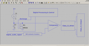
Somehere on these rich of information forums, I read that a DAC can be implemented by a network of resistors which are fed by the digital stream. However, they have a drawback as they rely on a stable logic power supply voltage and the analogue voltage depends on it. A ramp generator and voltage from the resistor chain (DAC) can be compared until equality at which point the pulse width ends. The pulse width starts at the start of the ramp.
If you took a DC power amplifier, fed by an ordinary unregulated unipolar supply, it's output would sit at Vcc/2 ordinarily - although you could move it to any point by changing the feedback. It would give you a "pass" regulator via the "upper" output transistor, but in addition a "shunt" regulator via the lower one. One would think via feedback you could make the output as "stiff" as can be; you could attach a load that both pulled current and dumped it back in and that output would not move, within realistic limits of course.If that is possible, that would be the smarter way.
You could do the same with any big class D amp; just turn it into a fixed output regulator having both source and shunt capability. Going into "real" powersupply land, one could follow the parallel multi-phase design philosophy of the multi 100's of Amp powersupplies used to power big CPU chips; "just" move the voltage capability into values needed for an audio amp. You can bet those designs handle a current release of 100+A down to 20 and step back up to 100+ with probably single digit millivolts of overshoot.
- Home
- Source & Line
- Digital Source
- A digital audio stream feeding 'almost' directly a Class-D driver & output stage?