Hi everyone!
I was trying this circuit from G.Velez (Gabevee) just to see the behaviour on LTSpice. I'm a newbie on electronics as well as in the use of Spice, so, independently if you like this circuit or not, can someone point out if there is some mistake in the original drawing or in my translation to LTSpice?
"Solid State Tube" Preamplifier
It seems to me that the freq response is somewhat restricted, and not 5 to 600Khz as claimed...
Thanks in advance
J
Attachments
Last edited:
Dunno. Can you show us what it looks like in LTSpice?... can someone point out if there is some mistake in the original drawing or in my translation to LTSpice?
What do you get?It seems to me that the freq response is somewhat restricted, and not 5 to 600Khz as claimed...
Your desire is an order 🙂
Attachments
Last edited:
I don't use Lt spice but a couple of quick thoughts.
At the top end R6 looks a problem, try 2k2
At the bottom end increase C6 to 220uf
At the top end R6 looks a problem, try 2k2
At the bottom end increase C6 to 220uf
In fact increase all the caps C3 C4 and C7 as well by a factor of ten. Also what load is on the end of C4 ?
As I say I don't use LT but whats the output impedance of the generator... if that's high that will add to HF roll off.
As I say I don't use LT but whats the output impedance of the generator... if that's high that will add to HF roll off.
The main problem is probably that you're using power mosfets instead of small-signal mosfets.
I see you changed a few other component values as well, but that shouldn't make much difference except for R13, which he says should not be changed, but you've changed from 330R to 2.2K. There's a capacitor missing too. That shouldn't affect high frequency response but might be important for something else?
btw I've no idea how I missed the schematic in your first post. I could swear it wasn't there when I first looked. 😕
As long as Mooly's changing everything anyway...
I'll agree with increasing C6, and vote for increasing C1 as well.
😛
I'll agree with increasing C6, and vote for increasing C1 as well.
😛
Thanks godfrey, you're right I missed to attach the picture by first, and then correct.. 😛
Ok can you suggest suitable signal mosfet from those in the default LTSpice library? (I've changed some componens figures in order to have the voltage figures pointed out in the original drawing, not any other reason than that)
Thanks again
J
Ok can you suggest suitable signal mosfet from those in the default LTSpice library? (I've changed some componens figures in order to have the voltage figures pointed out in the original drawing, not any other reason than that)
Thanks again
J
Nope, I'm pretty clueless regarding both LTSpice and mosfets. It looks like you can get the Spice model for BS170 from Fairchild over here though.Ok can you suggest suitable signal mosfet from those in the default LTSpice library?

That looks better. Remember at LF it's only the size of the various caps that are the limiting factor.
At hf the device properties do play a big role. Charging and discharging stray capacitance is the limiting factor. R6 is a real practical problem in that it sets limits on the negative output excursion i.e. if you load the output more (reduce R5) then the output will clip on the negative half cycle at higher outputs.
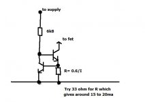
Experimenting with a simple current sink rather than a resistor might be interesting. Also try testing with squarewaves 😉
At hf the device properties do play a big role. Charging and discharging stray capacitance is the limiting factor. R6 is a real practical problem in that it sets limits on the negative output excursion i.e. if you load the output more (reduce R5) then the output will clip on the negative half cycle at higher outputs.
Experimenting with a simple current sink rather than a resistor might be interesting. Also try testing with squarewaves 😉
Thanks Mooly. What load size (R5 ) aproximates roughly the input of a typical SS amp?
10K, 20K , 100K ?
10K, 20K , 100K ?
It varies so always best to play safe and assume (as you have with R5) that it could be as low as 10k... a passive volume pot could be that for instance. Or it could be as high as 100k to 1meg.
In practice of course you won't be swinging the output between the rails but it's still good practice to have a good margin.
In practice of course you won't be swinging the output between the rails but it's still good practice to have a good margin.

You can't beat building it for real you know 😉 that really is revealing.
Yes 10k is a pretty safe value as most SS will be above that.
Yes 10k is a pretty safe value as most SS will be above that.
- Status
- Not open for further replies.
- Home
- Amplifiers
- Solid State
- A different (?) line level circuit