mhennessy said:
Don't forget that you can buy these direct from OnSemi.com - they might even send you samples 😉
Wow!! thanks for the useful info. I ordered samples. As I had to pay for the shipping $20 anyway, I decided to order heaps..enough to make dozens of MF A100 replicas if I'm inclined ... 🙂
Just replaced the most electro caps, but didn't test yet. Couldn't source 47uF 105degrees electro caps. Went to a component shop today where they sell Sam Xon brand (definitely chinese made) electro caps. Found one read 47uF, 105 degrees...cool. I just measured the actual capacitance, to get matching pairs right at the shop...41uF. Measured almost 50 caps in the shop and just one makes precise 47.00uF while all others less than 42uF. They were so consistently fell short of the own spec(I felt my multimeter was broken or something...)
It will be the same question, which was not answered yet.
kinda basic one, but with no formal education in electronics, I'd like to learn from professionals like you.
I have some problem in getting electro caps. Then why can't I use MKT or polyester caps instead? Is it the polarity that makes them different and decides where to use either type?
In an amp like this running in high temparature, I believe using less number of temparature-fragile electro caps ensures the long-term reliability...Ain't I correct?
otaku said:Wow!! thanks for the useful info. I ordered samples. As I had to pay for the shipping $20 anyway, I decided to order heaps..enough to make dozens of MF A100 replicas if I'm inclined ... 🙂
Just replaced the most electro caps, but didn't test yet. Couldn't source 47uF 105degrees electro caps. Went to a component shop today where they sell Sam Xon brand (definitely chinese made) electro caps. Found one read 47uF, 105 degrees...cool. I just measured the actual capacitance, to get matching pairs right at the shop...41uF. Measured almost 50 caps in the shop and just one makes precise 47.00uF while all others less than 42uF. They were so consistently fell short of the own spec(I felt my multimeter was broken or something...)
No problem - and wise to buy some spares, you might need them over the next few days 😉
Too be honest, I wouldn't have worried too much about the exact capacitor value - when designers spec a capacitor, they are normally very aware of the wide tolerances of electrolytic capacitors (maybe 10% to 100%). If you decided that you need a 22uF cap, it's not unreasonable to specify a 33uF or 47uF, just to ensure the actual components comfortably meet spec.
otaku said:It will be the same question, which was not answered yet.
kinda basic one, but with no formal education in electronics, I'd like to learn from professionals like you.
I have some problem in getting electro caps. Then why can't I use MKT or polyester caps instead? Is it the polarity that makes them different and decides where to use either type?
In an amp like this running in high temparature, I believe using less number of temparature-fragile electro caps ensures the long-term reliability...Ain't I correct?
The biggest problem is likely to be the physical size of the components - it might be tricky fitting them in. Of course, MF could have designed the PCB to accomodate them, but they are much more expensive than electrolytics. The usual bottom line is $$$
But, you're right about reliabilty 😉
Hope this helps,
Mark 😉
BobEllis said:"Franks's Theory," at least as I read it, is that either you have lost a rail or that an output transistor has failed in a short circuit. This would put rail voltage on the output and cause the opposite transistor to run extra hot (since it now is dissipating twice the power)
Are you saying that the right channel still works and only the left is dead? This would change the troubleshooting picture.
BobEllis
Thanks for the kind explanation.
I was rather hooked up by someone else's (perhaps Mark), and since then, somehow have forgotten to reply to you. Both channels are dead.
Perhaps short circuit has slaughtered all 4 transistors, I guess 🙂
I'll upgrade all trannies to MJ1500Xs anyway, and waiting for the shipment from OnSemi..
I had long planned to replace all the electro caps with 105degrees anyway. Transistors were added to the blacklist during the work. While I can't figure out anything else that could have failed this amp, replacing caps and trannies is likely to put this back to work. (Ah...power supply caps are...too expensive...and I hope they are ok without any replacement...)
Due to the funny enclosure design, and no powerful fan available, I'm reluctant to power it up and do any measurement around the circuit with top lid off..
otaku said:Both channels are dead.
Hmm - I hadn't realised that both channels were dead - should have read the title of the thread more carefully 😉
In this case, maybe it's time to check the power supply very carefully. Does the power LED light up? Can you measure the power supply rails (I understand your reluctance to run the amp without a lid, but powering it up for a couple of seconds at a time should be ok - get some croc-clip leads for your multimeter so you don't have to waste any time...
Cheers,
Mark 😉
I have just replaced all the transistors with MJ2955/2N3055 pairs. (OnSemi somehow canceled my sample order, didn't want to bother to wait, so bought them from local parts dealer) and all the electro caps are now 105degrees.
I hooked it up with one speaker and cd player and the original problem still remains. Even no hiss or noise..It's completely silent..
Perhaps I should fiddle around with multimeter now... Even if I'm pretty good at soldering, not much experienced with troubleshooting. I understand I should connect the black probe to the GND and measure the voltage? (reluctant to disclose my ignorance... but it's my first high-voltage project and won't do any harm to make everything sure again and again...)
BTW, everyone happy easter!!
I hooked it up with one speaker and cd player and the original problem still remains. Even no hiss or noise..It's completely silent..
Perhaps I should fiddle around with multimeter now... Even if I'm pretty good at soldering, not much experienced with troubleshooting. I understand I should connect the black probe to the GND and measure the voltage? (reluctant to disclose my ignorance...
but it's my first high-voltage project and won't do any harm to make everything sure again and again...) BTW, everyone happy easter!!
I measured the voltage across the reservoir caps. C1,C2,C3 measured 42V, while C4 gives 0.9mV!! I'm now confident that this must be one of the reason. Does it mean both channel can completely die? Can I simply change C4 only ? Obviously the original brand caps are not available and 22000uF is extremely expensive..
Why is this caps so big in value anyway? 4x10000uF shouldn't be enough?
Another thing is regarding TO3 transistors.
2N3055 is NPN and MJ2955 is PNP. Both should pass 3 tests
# The base-emitter (BE) junction should behave like a diode and conduct one way only.
# The base-collector (BC) junction should behave like a diode and conduct one way only.
# The collector-emitter (CE) should not conduct either way.
They all passed the test before I mounted them to the heatsink. I made sure there is no short. Then measuring the conductivity on PCB, 3 of them failed the test. It's no good sign, right?
As a matter of fact, the TO3 mouting kit I bought had a washer with soldering extension whose hole is smaller than the plastic bush! I reluctantly soldered the collector on the shell. Perhaps too much heat destroyed the trannies? According to the datasheet, the operating and storage junction temparature range is -65
~200, which made me believe soldering on the case won't do too much harm..Hmm...I should replace them again, uh?
otaku said:I measured the voltage across the reservoir caps. C1,C2,C3 measured 42V, while C4 gives 0.9mV!! I'm now confident that this must be one of the reason. Does it mean both channel can completely die? Can I simply change C4 only ? Obviously the original brand caps are not available and 22000uF is extremely expensive..
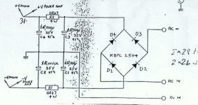
No, it means that R2 has failed open-circuit. Replace that before worring about the other stuff. Look at the power supply schematic (I know it's from my A1, but they're similar)
An externally hosted image should be here but it was not working when we last tested it.
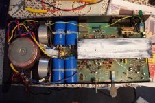
Wow, you're absolutely right, Mark. R1,R2 are fuses in my PCB(not sure if it is originally so) as you can see in the attached image. One of the fuse was blown before and I replaced already. But after reading your post, I rechecked to find that one had been blown again.
It's kinda funny as when the fuse is mounted in socket, if I measure conductivity both end of the fuse , it shows it is closed. But once taken off, it is obviously open. So your diagnosis was correct. Thanks!!!
1. Can I simply replace it with some wirewound 0.47ohm resistor? Or should it be kept as it is and just a new fuse should be replaced? It's so called bleeder resistor that discharges the caps when turned off, I guess?
2. According to Randy Slone's book, I feel that 22000uF anyway is a bit excessive. Bigger ones wouldn't do any harm, but if replacement is needed, 10000uF will do the job without any vicious effect?
3. The reservoir caps are rated 35v, while giving out 42v. They've been working ok, so no problem. But 42v is a bit too high, while it's supposed to be 32v, I guess?
4. Power LED are remaining bright for a minute or so even it's turned off. Is it normal?
Thanks x 10000!!!
Attachments
otaku said:Wow, you're absolutely right, Mark. R1,R2 are fuses in my PCB(not sure if it is originally so) as you can see in the attached image. One of the fuse was blown before and I replaced already. But after reading your post, I rechecked to find that one had been blown again.
It's kinda funny as when the fuse is mounted in socket, if I measure conductivity both end of the fuse , it shows it is closed. But once taken off, it is obviously open. So your diagnosis was correct. Thanks!!!
1. Can I simply replace it with some wirewound 0.47ohm resistor? Or should it be kept as it is and just a new fuse should be replaced? It's so called bleeder resistor that discharges the caps when turned off, I guess?
Not sure... I believe that the origional amp would have had resistors, but fuses are a good idea, especially at this stage. I'll check my archives this weekend - I think I've got a copy of the correct schematic.
otaku said:2. According to Randy Slone's book, I feel that 22000uF anyway is a bit excessive. Bigger ones wouldn't do any harm, but if replacement is needed, 10000uF will do the job without any vicious effect?
Again, if I've got the correct schematic then I should be able to confirm this at the weekend. Bigger values will cause the rectifier and mains transformer to run warmer - not recommended...
otaku said:3. The reservoir caps are rated 35v, while giving out 42v. They've been working ok, so no problem. But 42v is a bit too high, while it's supposed to be 32v, I guess?
Actually, this is bad! You shouldn't exceed the working voltage of a capacitor under any circumstances - if you do, there is a very serious risk of them exploding. I'm not kidding!
So, are you definitely sure there's 42V across them? Are you measuring this at the tags of the capacitors? Does the voltage rating of the amp match your local mains supply? How accurate is your volt meter?
As the power supply is running with no load, it's normal to find a bit more than the normal 32V. But not 42V...
otaku said:4. Power LED are remaining bright for a minute or so even it's turned off. Is it normal?
Yes, this is fine.
Thanks for the picture. I've never actually seen inside an A100, so please feel free to post some more. You could send them to my home email rather than posting them here if you prefer...
Cheers,
Mark 😉
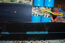
A100
If the fuse keeps blowing, It means that either there is a short from the +24v rail to ground or more likely, a fault in one of the channels which is causing too much current to flow through one of the output transistors.
Can I suggest that you don't replace any further components until you have established exactly what and where the fault is. Definitely don't think about any modifications at this point or you are likely to end up with an expensive dead amplifier which will never work again.
You have established so-far that the first part of the power supply is alive and well. Next, you need to work out which channel is faulty. I normally do this by disconnecting the supply to each channel in turn, powering up the amp slowly on a variac and measuring the current being drawn. Chances are that one channel will be fine and can be left alone.
I don't have a schematic for the a100 anymore but it uses a fairly simple push-pull design set for an idling current of about 600mA I think.
Unless the fuse is blowing violently (blackened tube etc) the output transistors are probably fine. I would be looking further back in the circuit for shorted transistors, leaky capacitors etc. Again, the easiest way to do this is by using a variac and a good multimeter to check voltages at the different stages of the circuit.
Push-pull power amplifiers are not that easy to troubleshoot as they are mostly DC coupled meaning that a faulty component anywhere in the circuit can cause the output transistors to draw too much current and melt or blow fuses.
Whatever you do, don't think about replacing the fuse with a low value resistor. The fuses are there to prevent serious damage to the rest of the amp in the event of a fault condition such as the one that you have.
Also, I wouldn't worry too much about the high off-load voltages across the power supply. When the amp is running, it would be drawing over an amp at idle unlike a more conventional class AB circuit so voltages should return to normal once the output stages are fixed and drawing the correct load. Obviously it's not a good idea to leave the unit powered up for any length of time in it's present condition - 42volts across a 35v rated cap isn't good!
If the above doesn't make much sense to you then I suggest that you put the lid back on and get the amp to someone who has the knowledge and test equipment necessary to sort it out for you.
I would be happy to repair it for the cost of any parts involved, however seeing as we live on different sides of the planet I think postage costs might be excessive.
good luck!
42v!!
Had another read over what I have just written. 42v is quite a bit higher than I would have expected. Is your meter reading accurately? unless it's a good one, I would have my suspicions about that reading. Don't suppose you disconnected the transformer secondaries at some point? If so, check they are back where they should be.
Had another read over what I have just written. 42v is quite a bit higher than I would have expected. Is your meter reading accurately? unless it's a good one, I would have my suspicions about that reading. Don't suppose you disconnected the transformer secondaries at some point? If so, check they are back where they should be.
Re: A100
Remember the white **** on the heatsink? 🙂
Fortunately, it looks like the fuse was blown during the careless soldering. Stupid me, but I don't make the same mistake..I have sharp learning curve 🙂 Not as serious as what you are suggesting. But I'll look into these problems too.martinab2 said:If the fuse keeps blowing, It means that either there is a short from the +24v rail to ground or more likely, a fault in one of the channels which is causing too much current to flow through one of the output transistors.
Good suggestion. I'll replace the fuse and transistors though, as I know they are wrong anyway. If it doesn't fix, I'll then take it to the service person. I'm sure that I didn't make it any worse, but what I have now is all caps rated at 105degrees.
Can I suggest that you don't replace any further components until you have established exactly what and where the fault is.
Very kind of you. Yes, it's too bad I live too far away.
I would be happy to repair it for the cost of any parts involved, however seeing as we live on different sides of the planet I think postage costs might be excessive.
good luck!
I'll check if my meter is ok. I don't think I'm missing any transformer wiring...They are back to where they should be..
Is your meter reading accurately? unless it's a good one, I would have my suspicions about that reading. Don't suppose you disconnected the transformer secondaries at some point? If so, check they are back where they should be.
Remember the white **** on the heatsink? 🙂
Attachments
it is worth the trouble
Otaku,
You go through the same process as I did some months ago. I bought a secondhand a100 that did not work properly and went to the repairman just too many times during the last years. Of course, the price was in accordance with these facts (only 50 Euro).
I took me a complete day and a lot of parts but now I have a so good as new A100 that works very beautifully. It is worth the time and trouble: this really is an amp that sings.
I did:
* replace all small caps.
* replace the main caps (blackened).
* replace the bigger power resistors (darkened)
* replace the power transistors by MJ802/4502 (here was the real problem of the amp not working properly).
Furthermore:
* several versions of these amps have different idle current ranging from 600 mA to 1,5A. After a lot of trying and testing I choose 600 mA as best sound/longest life combination. This is done by inserting value 2M7 x 2 in the circuit and .47 Ohm/5 Watt in the output (sometimes this is .22 which doubles the current). The circuit can be found in this forum at several places.
* I disconnected the pre- and main amps by sacrificing the tape in-out connector and making them pre-in main-out. Especially the main-amp is very special and worthy of a better (tube) preamp.
After one month of listening to the as new A100 I was so happy about the sound (comparing it to amps costing 5 times as much) that I decided to built myself from scratch 2 monoblocks using 300 VA transformer per channel etc). Remember that the generic circuit of the A1/100/MA50/MA100 was tested in HFNRR of 1988 as coming close to ARC D240 and Krell KSA80 sound, the reviewer wondering what the hell could be the explanation of this!!!
I put a picture of my veroboard A100 somewhere on this forum.
Rudy
42v
Hmm..I checked with another meter and the same result- 42V.
NZ has 240v/50hz, so UK made amps should be running without any main power mod.
Transformer secondary shows 26-0-26V. Looks normal.
Hmm..I checked with another meter and the same result- 42V.
NZ has 240v/50hz, so UK made amps should be running without any main power mod.
Transformer secondary shows 26-0-26V. Looks normal.
Re: it is worth the trouble
rmgvs,
Glad to hear from you. I remember I saw your postings in another thread titled "weird behaviour ...". Discussions in the thread is the main reason I decided to keep this troublemaker and never let go...at least I have many experts who really know this poor thing, and I expected I can sort it out with your help if anything goes wrong! Yes, the time has come 🙂
I'm eventually planning to all the works you did. MJ802/4502 are good replacement compared to MJ15003/15004?
I did:
* replace all small caps.
* replace the main caps (blackened).
* replace the bigger power resistors (darkened)
* replace the power transistors by MJ802/4502 (here was the real problem of the amp not working properly).
* I disconnected the pre- and main amps by sacrificing the tape in-out connector and making them pre-in main-out. Especially the main-amp is very special and worthy of a better (tube) preamp.
I have the circuit schematic and fortunately, my circuit has 2M7*2 already and 0.47ohm as well. Taken 2M7*2 off, I guess it becomes class AB, doesn't it?
Furthermore:
* several versions of these amps have different idle current ranging from 600 mA to 1,5A. After a lot of trying and testing I choose 600 mA as best sound/longest life combination. This is done by inserting value 2M7 x 2 in the circuit and .47 Ohm/5 Watt in the output (sometimes this is .22 which doubles the current). The circuit can be found in this forum at several places.
You're the man! Much tidier than the original. I'm impressed, really. Thanks!
I put a picture of my veroboard A100 somewhere on this forum.
Hi otaku,
Thanks for the picture. I assume those are fans between the transformer and PCB?
I'm still troubled by this 42V. You say that the transformer is giving 26-026, which sounds right - this should give DC of around +/-36V off-load - not 42V. Check very carefully for broken tracks and bad soldering, because something very weird and probably silly is going on here...
Those fuses are definately mods, but you'd be advised to leave them in there for now - they might save your new output transistors.
My copy of the schematic is a bit strange about the smoothing cap values - see what you make of them:
Hi rmgvs - must admit that I didn't see your Vero A100 before - excellent! How does it compare to a stock model?
Attachments
Hi Mark, Yes, these two are fans. Good eyesight!mhennessy said:Hi otaku,
I assume those are fans between the transformer and PCB?
Is it possible for KBPC25 to fail?
I'm still troubled by this 42V. You say that the transformer is giving 26-026, which sounds right - this should give DC of around +/-36V off-load - not 42V. Check very carefully for broken tracks and bad soldering, because something very weird and probably silly is going on here...
various
Otaku,
If you take the 2M7 the amp will draw about 50 mA current, I did not listen to this arrangement, but I guess it will sound okay, but it takes some of the essence of the A-series away.
In my replica I tried to do everything 'better' thus used the 15003/004 couple from ON-Motorola. In the repair of the original I used 802/4502 from Thomsom/SGS. I did compare the two and have to admit I could not in any way tell the difference. Well, I couldn't resist trying the good old 2955/3055 (Motorola also) also and here I could hear differences clearly (for the worse, but mind you, still very good).
In repairing an old A1 I had to replace the diodes (your KBPC in the A100) and this causes strange things in voltages (not symmetrical), so in your case I would certainly change this thing anyway.
Mark,
Can I hear differences between the original and my replica? Let me first say that the original is that good that you must not think to better the original just by throwing in some fancy components. On the contrary: it took me quite some fiddling to (slighty) better the original. The right 139/140 made quite a difference to the sound and the effect of the feedback cap's (22-33 pF) was also greater than I expected (mica, MKP etc could make the amp sound from (too) dull to (too) bright). Now I think my replica sounds more open, with crisper highs, better stereo images while keeping the 'warm' full-bodied character that makes the A1/100 so special. The original, especially after many years of use, sounds slightly too warm and is not so precise or pin-pointed. But the main thing is I do no need fans and keep my amps luke warm so I hope it will last for 40 years or so. Strange effect that I do not understand: I started my amp with more than 1 Amp of idle current and it does not sound as good as with 600 mA (this is contrary to findings in other amps).
coupling caps
I forgot to mention that I used a very big range of different caps at the input ranging from polyester to polyprop, Wima, Ero, Solen, you name it. Differences could easily be heart, that is true. One wrong type in this place and away is your special amp, no matter how good the rest of your components are. I thought that replacing the electrolytics would better the sound anyway: forget it, this is not the case. The original electrolytics are not that bad at all (another surprise).
I forgot to mention that I used a very big range of different caps at the input ranging from polyester to polyprop, Wima, Ero, Solen, you name it. Differences could easily be heart, that is true. One wrong type in this place and away is your special amp, no matter how good the rest of your components are. I thought that replacing the electrolytics would better the sound anyway: forget it, this is not the case. The original electrolytics are not that bad at all (another surprise).
- Home
- Amplifiers
- Solid State
- a dead Musical Fidelity A100