Now I just need to learn how to use labs memory scope so I can save the samples.
User manual to the rescue.
User manual to the rescue.
I think I'm going to build this.
I have all the supply parts coming and I've pre-made the chassis. I need to switch my transistors in the end to a lot bigger sinks and re-bias then.
I'll be updating when I get to mend the last bits for the chassis and I get bigger sinks.
I have all the supply parts coming and I've pre-made the chassis. I need to switch my transistors in the end to a lot bigger sinks and re-bias then.
I'll be updating when I get to mend the last bits for the chassis and I get bigger sinks.
Good for you 🙂 Take it slowly and check as you go along and you should end up with a cracking amplifier.
Umm, before I start. I'm looking to determine, if you don't have any suggestions, to determine what test to conduct, and if I could get some advice how to determine the measurements.
I'm now looking into Frequency response, total harmonic distortion, noise, dynamic range, phase shift/transfer, damping.
I only have one book and internet, it would be good to have some insight.
I'm now looking into Frequency response, total harmonic distortion, noise, dynamic range, phase shift/transfer, damping.
I only have one book and internet, it would be good to have some insight.
You need a decent scope for starters...
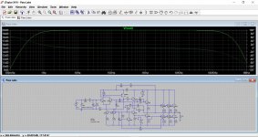
Frequency response can be measured with the aid of a decent (it doesn't need be brilliant) sine wave generator or function generator that covers from say 1Hz to 1MHz.
Phase shift is easily measured on a scope by comparing input and output.
Distortion is probably best measured using a PC soundcard and suitable software.
Dynamic range. That's an interesting one. That is the ratio of the highest undistorted output to the lowest 'usable' level, in other words before the output becomes buried in the noise.
Damping factor would have to be deduced by a couple of measurements, or driving another amplifier into the output of the amp under test (via a resistor) and looking at the signal that actually develops across the speaker output of the amp under test.
A lot of the above can be arrived at from a decent simulation.
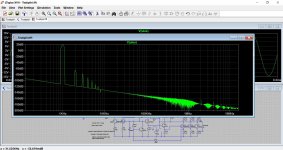
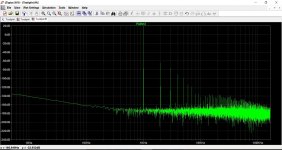
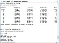
I'm wondering about the FFT and DHT, I've ran them for my circuit and in the spectral window it looks quite nice but the in SPICE log the total harmonic distortion is over 1%. How could I get it lower?


also at maximum power for 6 ohms the output power goes quite high 35 Watts
also at maximum power for 6 ohms the output power goes quite high 35 Watts
This was all a long time ago for me 🙂
You are going to have to post the .asc file you are using for me to try and see where it is going wrong. I did an FFT back in post #15
A-class amplifier simulation
You are going to have to post the .asc file you are using for me to try and see where it is going wrong. I did an FFT back in post #15
A-class amplifier simulation
How can I be sure my bias is at the correct level?
I had my bias set 585-610 since there is where I found it operating.
I had my bias set 585-610 since there is where I found it operating.
For 8 ohm speakers Nelson recommended setting to give around 125mv across R22, so that would be 0.56A per output pair.
Thanks. Try adding this as a .op command.
Code:.options maxstep=0.48831106u .option plotwinsize=0
Or try this one:
Code:
.option distortion = 0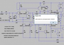
I'm only finding low resistor values for bias all under 1400... The lowest I got was 230 mW at R22 for 6 ohms.
R22 must be kept at 0.22 ohms (and all the other emitter resistors). To go higher increases the dissipation in the resistor and reduces efficiency. There are other downsides as well. So they have to be 0.22 ohm.
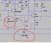
The simulation seems incredibly sensitive to transistor models used, so much so that I think the real build would be far more forgiving.
For example changing the bias regulator to a higher gain BC337-40 not only alters the value of bias setting resistor but also makes it super sensitive to fractions of a decimal place. No real build would behave like that. We are talking 0.0001 ohms difference in value changing the current by over 1 amp.
So you need to see how the real build behaves now with the devices you are actually using and move on from the simulation. It is an interesting one though 🙂
Attachments
- Status
- Not open for further replies.
- Home
- Amplifiers
- Pass Labs
- A-class amplifier simulation