A headphone buffer circuit just for fun.
With lateral MOSFETs at 150mA bias, you can put an OPA604 or similar upfront with the buffer inside the NFB loop.
Then you will even have gain and reduce Zout enough to drive speakers.
Patrick
.
With lateral MOSFETs at 150mA bias, you can put an OPA604 or similar upfront with the buffer inside the NFB loop.
Then you will even have gain and reduce Zout enough to drive speakers.
Patrick
.
Attachments
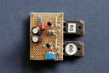

Just to prove that it works as intended, I grabbed what I had in the drawer and made a quick-and-dirty Vero-prototype.
I did not have any Exicons on hand, so I used 2SK1058 instead.
They were also not well matched, and I did not both to trim either.
Even then, with nominal calculated resistor values, bias was 125mA and DC offset 30mV, as expected.
Both bias and DC offset were rock steady over an hour.
The current ratio was easily adjustable via a trimmer at R5a/b position, as intended.
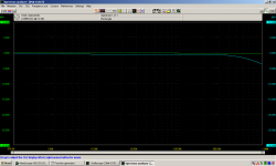
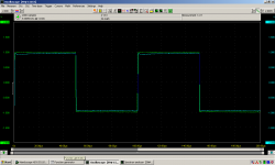
Bandwidth was 900kHz -3dB, and 10kHz square wave has a tiny single overshoot.
So everything works as in simulations.
So much for now, till proper PCBs and matched devices are available. 🙂
Patrick
.
I did not have any Exicons on hand, so I used 2SK1058 instead.
They were also not well matched, and I did not both to trim either.
Even then, with nominal calculated resistor values, bias was 125mA and DC offset 30mV, as expected.
Both bias and DC offset were rock steady over an hour.
The current ratio was easily adjustable via a trimmer at R5a/b position, as intended.
Bandwidth was 900kHz -3dB, and 10kHz square wave has a tiny single overshoot.
So everything works as in simulations.
So much for now, till proper PCBs and matched devices are available. 🙂
Patrick
.
Attachments
The rail voltage is limited by what the JFET can take.
In the case of J113, it is limited to 35V, so +/-17V rails.
JFE150 gives you 5V extra, or +/-20V, for a lot more money.
For me not worth it.
If you want to go (much) higher, you need to cascode the JFETs.
Then +/-50V is technically possible.
Patrick
In the case of J113, it is limited to 35V, so +/-17V rails.
JFE150 gives you 5V extra, or +/-20V, for a lot more money.
For me not worth it.
If you want to go (much) higher, you need to cascode the JFETs.
Then +/-50V is technically possible.
Patrick
As an addendum to post #5, the J113 from Philips is 40V, same as the JFE150 from TI.
Still can be had from ebay for reasonable money.
But probably only important for speakers and not headphones.
Patrick
Still can be had from ebay for reasonable money.
But probably only important for speakers and not headphones.
Patrick
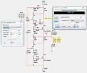
I will go for +/-17 volt.
And use J113 in the schematic in the PDF.
I will not build it. Only do some simulations.
Unfortunetly I can not use .asc files.
Because I use Multisim.
I have J113 and ECX10N20 spice files.
And use J113 in the schematic in the PDF.
I will not build it. Only do some simulations.
Unfortunetly I can not use .asc files.
Because I use Multisim.
I have J113 and ECX10N20 spice files.
My J113 model:
IDSS = 18.9mA
1mA at VGS -1.07V
If I can't use that model at 150mA in the EXICON I will go for some alternative JFET.
My ECX10N20 shows VGS 0.82V at 150mA.
How about using LSK170, LSK189 or the duals LSK389 and LSK489?
IDSS = 18.9mA
1mA at VGS -1.07V
If I can't use that model at 150mA in the EXICON I will go for some alternative JFET.
My ECX10N20 shows VGS 0.82V at 150mA.
How about using LSK170, LSK189 or the duals LSK389 and LSK489?
Your simulation looks fine to me.
If you read the article, you will know that none of the above would do.
Id at -0.82 Vgs just too small.
2SK246GR / 2SK208 GR will also do, and can be used with +/-25V rails.
You just need to watch dissipation with 2SK208 ( active part at Mouser / DK ).
And model available directly from Toshiba.
Actually 2SK246/208 would be a better match with 2SK1058.
Patrick
How about using LSK170, LSK189 or the duals LSK389 and LSK489?
If you read the article, you will know that none of the above would do.
Id at -0.82 Vgs just too small.
2SK246GR / 2SK208 GR will also do, and can be used with +/-25V rails.
You just need to watch dissipation with 2SK208 ( active part at Mouser / DK ).
And model available directly from Toshiba.
Actually 2SK246/208 would be a better match with 2SK1058.
Patrick
- Home
- Amplifiers
- Headphone Systems
- A Casual Fling with Fetlingtons -- The Fling Headphone Buffer with Adjustable H2