Is the capacitance gain worth the much slower time response?
I'm really not sure what you are after with your question. There is no problem with time response.. please let me know where/if you see one. There are several benefits, so I guess the answer is yes... totally worth it. Can you be more specific with your question?
I researched the external searches you suggested and re-read your description above. It appears the circuit is only effective for low peak current demands. When using a smaller VA transformer, there will be no way to keep the supply rails from sagging as would "real " large capacitors. One reference suggested that the harmonic structure of the ripple would be "improved". Ripple is small and a good power amp should have high PSRR, so I fail to see the relevance of that claim.
"Effective" meaning what exactly? The circuit works as intended and happens to fill a couple of needs that I have. I have already explained the benefits and the applications for the circuit in my earlier posts.I researched the external searches you suggested and re-read your description above. It appears the circuit is only effective for low peak current demands.
When using a smaller VA transformer, there will be no way to keep the supply rails from sagging as would "real " large capacitors. One reference suggested that the harmonic structure of the ripple would be "improved". Ripple is small and a good power amp should have high PSRR, so I fail to see the relevance of that claim.
You are correct. This is NOT a regulated supply, and the rails will sag but the ripple will remain low. That is actually the desired/intended effect.
Ripple can be an issue for class-A and some class-D amplifiers but is not typically a problem for a class-AB amp due to its high PSRR.
Update: unfortunately due to severe procrastination I still have not built one of these!
I now have a couple of amp projects lined up and I need one of these so I'm hoping to finally get my act together and at least solder the parts to the darn pcb.
I now have a couple of amp projects lined up and I need one of these so I'm hoping to finally get my act together and at least solder the parts to the darn pcb.
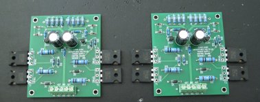
Actually, I built two! I still have not soldered in the output devices. I need to dig up a heat sink and some standoffs. Then I will try to build a supply and check out how they function. Pic attached.
The CAD program I used to design the PCBs is called "Target3001". Its free for simple circuits like this (the free version has a limit on the number of components or something like that). Its pretty easy to use and has a reasonable autorouter that you can use when you are just starting out your layout. I did all the circuit simulating in TINA, however.
The CAD program I used to design the PCBs is called "Target3001". Its free for simple circuits like this (the free version has a limit on the number of components or something like that). Its pretty easy to use and has a reasonable autorouter that you can use when you are just starting out your layout. I did all the circuit simulating in TINA, however.
Attachments
Last edited:
- Status
- Not open for further replies.
- Home
- Amplifiers
- Power Supplies
- a Capacitance Multiplier with over-voltage protection