My projects lately almost always start with me revisiting an earlier project and deciding to completely re-do it. (see http://www.diyaudio.com/forums/multi-way/256074-long-road-3-way-active-speaker.html which is another in-process project)
This one started as a pair of 2-way speakers for my workshop. I had some Focal 6W3253 6-inch drivers, and I'd always been fascinated with Focal's better drivers- based on my hearing some of their finished speakers. So, OK, a 6W3253. I also had a pair of Fountek Neo CD 3.0 ribbons lying around. I tried to design a crossover but couldn't get anything I was confident would work, so I paid Madisound to do a LEAP xover for me. I put the drivers in a Parts Express 0.75 cu ft box, sealed alignment.
Focal 6W3253 full range measurement with 1/6 octave smoothing

Here's what the enclosure predicted T-S curve looks like, not a bad F3

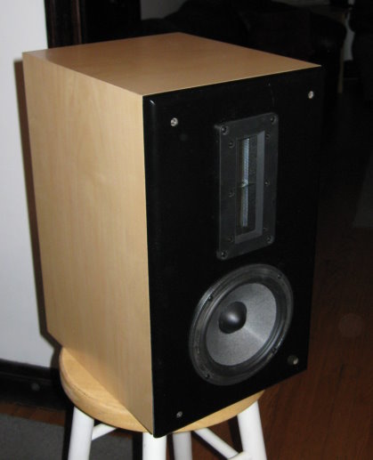
Here's what the speaker looks like
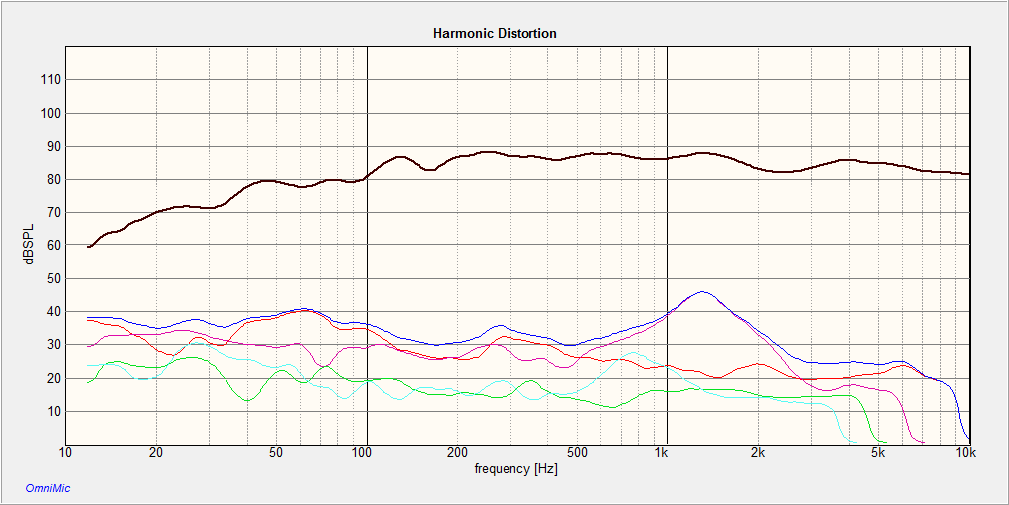
So this sounded ok, here's a response curve and harmonic distortion curves I ran, at 90 dB SPL at 3 meters with THD being in blue, 2nd harmonic in magenta. You can see a bit of a peak in distortion near the 2500 Hz crossover point.
OK so this is not really terrible but just did not satisfy me. And in the end, these 0.75 cu ft (21.24 L ) cabinets were just too big for my workshop; I ended up building a pair of 0.25 cu. ft. sealed boxes with SEAS EXCEL SEAS W15CY-001 5.5" woofer and 'Millennium' tweeter with a crossover designed for me by Rick at Selah Audio. These have worked just fine, they sound great- a wonderful detailed neutral sound.
But back to these 0.75 Cu Ft 2-ways... I took them out of storage to use for another location, and after to listening to them, they just were not RIGHT. Hard to describe what I'm hearing.... but the response balance is not right. No midbass, is how I'd characterize it. Extended treble, and the midrange is good - very detailed- but bass is not right. There's some sense of bass 'extension' but overall it just doesn't sound musical.
BACK TO THE DRAWING BOARD - in looking for midwoofers that would work with this 0.75 cu ft enclosure, I didn't find any that I really liked which would work in a sealed alignment, but with a port the Satori MW16P seems like it would work fine.
Satori MW16P T-S prediction

So this is actually a little less flat and a little less extended than the Focal woofer, but the Satori paper cone doesn't have the ~3 kHz breakup that the Focal has with it's stiff "W" cone, so it appeals to me more... and while the Focal is rated 1.5 dB more efficient, I plan on now going to an ACTIVE 2-way...
Doing a crossover with a MinDSP digital xover module is easier, I think, than trying to design a passive crossover. In particular, it is much easier to try out different slopes, crossover points and overall tweeter / midwoofer levels with an active system. So, OK, I am going to use the Mini DSP 2-way.
Now when I came to figuring out what amplifiers to use, I have some laying around but I thought- why not build a dedicated crossover / biamp chassis?
I almost went with a Pass Aleph 3 clone class A design for the LF amp, but cost of power supply and heatsinking kept me from going down that road. Besides, I already have enough solid-state class A amps, I don't need yet another space heater. So I went with a T-amp class D design, using a Tripath TA2022. This will give me about 27 watts into the woofer at 0.1% THD and more power for peaks at higher but still tolerable distortion levels. This **SHOULD** give me over just 100 dB at my listening position from the midwoofers; if this is not enough amplifier power, I will then go with Hypex UcD180HG modules, a more expensive proposition.
For the ribbon tweeters- which are quite sensitive ( 97 dB 2.87 v / 1 m) I don't need much power - especially since I will be crossing over around 3 kHz. I've chosen a Hartung SET amp, with about 3~4 watts / ch. - purchased off eBay for under $100 complete with it's power supply.
So I'll put these items - crossover, treble SET amp and bass Tripath amp- all in one chassis. But then I thought - why not integrate the crossover's control computer with the chassis, and also use the computer as a media player- an Internet Radio "tuner" and also a player for my networked music server's 60,000 FLAC files.... so I got a Lenovo Windows 8.1 8 inch tablet (again, less than $100 on eBay) - it has to be Windows, the MiniDSP software is Windows- and also I need the parts to bring SPDIF audio out of the tablet's USB connection, the MiniDSP can use analog or SPDIF inputs.
It's going to take quite some building to create a chassis that can accommodate this tablet - I plan to make a kind of "dock" for it on the chassis... I might also incorporate a USB-connected CD drive too just 'cause it's so cheap to do. And, in addition to the WOOFER L/R and TWEETER L/R outputs, I'll want a pair of fullband RCA line outputs for a headphone amp... like the BETA 22 that I built
The parts are all arriving now.... I'll post more as I go.
This one started as a pair of 2-way speakers for my workshop. I had some Focal 6W3253 6-inch drivers, and I'd always been fascinated with Focal's better drivers- based on my hearing some of their finished speakers. So, OK, a 6W3253. I also had a pair of Fountek Neo CD 3.0 ribbons lying around. I tried to design a crossover but couldn't get anything I was confident would work, so I paid Madisound to do a LEAP xover for me. I put the drivers in a Parts Express 0.75 cu ft box, sealed alignment.
Focal 6W3253 full range measurement with 1/6 octave smoothing
Here's what the enclosure predicted T-S curve looks like, not a bad F3
Here's what the speaker looks like
So this sounded ok, here's a response curve and harmonic distortion curves I ran, at 90 dB SPL at 3 meters with THD being in blue, 2nd harmonic in magenta. You can see a bit of a peak in distortion near the 2500 Hz crossover point.
OK so this is not really terrible but just did not satisfy me. And in the end, these 0.75 cu ft (21.24 L ) cabinets were just too big for my workshop; I ended up building a pair of 0.25 cu. ft. sealed boxes with SEAS EXCEL SEAS W15CY-001 5.5" woofer and 'Millennium' tweeter with a crossover designed for me by Rick at Selah Audio. These have worked just fine, they sound great- a wonderful detailed neutral sound.
But back to these 0.75 Cu Ft 2-ways... I took them out of storage to use for another location, and after to listening to them, they just were not RIGHT. Hard to describe what I'm hearing.... but the response balance is not right. No midbass, is how I'd characterize it. Extended treble, and the midrange is good - very detailed- but bass is not right. There's some sense of bass 'extension' but overall it just doesn't sound musical.
BACK TO THE DRAWING BOARD - in looking for midwoofers that would work with this 0.75 cu ft enclosure, I didn't find any that I really liked which would work in a sealed alignment, but with a port the Satori MW16P seems like it would work fine.
Satori MW16P T-S prediction
So this is actually a little less flat and a little less extended than the Focal woofer, but the Satori paper cone doesn't have the ~3 kHz breakup that the Focal has with it's stiff "W" cone, so it appeals to me more... and while the Focal is rated 1.5 dB more efficient, I plan on now going to an ACTIVE 2-way...
Doing a crossover with a MinDSP digital xover module is easier, I think, than trying to design a passive crossover. In particular, it is much easier to try out different slopes, crossover points and overall tweeter / midwoofer levels with an active system. So, OK, I am going to use the Mini DSP 2-way.
Now when I came to figuring out what amplifiers to use, I have some laying around but I thought- why not build a dedicated crossover / biamp chassis?
I almost went with a Pass Aleph 3 clone class A design for the LF amp, but cost of power supply and heatsinking kept me from going down that road. Besides, I already have enough solid-state class A amps, I don't need yet another space heater. So I went with a T-amp class D design, using a Tripath TA2022. This will give me about 27 watts into the woofer at 0.1% THD and more power for peaks at higher but still tolerable distortion levels. This **SHOULD** give me over just 100 dB at my listening position from the midwoofers; if this is not enough amplifier power, I will then go with Hypex UcD180HG modules, a more expensive proposition.
For the ribbon tweeters- which are quite sensitive ( 97 dB 2.87 v / 1 m) I don't need much power - especially since I will be crossing over around 3 kHz. I've chosen a Hartung SET amp, with about 3~4 watts / ch. - purchased off eBay for under $100 complete with it's power supply.
So I'll put these items - crossover, treble SET amp and bass Tripath amp- all in one chassis. But then I thought - why not integrate the crossover's control computer with the chassis, and also use the computer as a media player- an Internet Radio "tuner" and also a player for my networked music server's 60,000 FLAC files.... so I got a Lenovo Windows 8.1 8 inch tablet (again, less than $100 on eBay) - it has to be Windows, the MiniDSP software is Windows- and also I need the parts to bring SPDIF audio out of the tablet's USB connection, the MiniDSP can use analog or SPDIF inputs.
It's going to take quite some building to create a chassis that can accommodate this tablet - I plan to make a kind of "dock" for it on the chassis... I might also incorporate a USB-connected CD drive too just 'cause it's so cheap to do. And, in addition to the WOOFER L/R and TWEETER L/R outputs, I'll want a pair of fullband RCA line outputs for a headphone amp... like the BETA 22 that I built
The parts are all arriving now.... I'll post more as I go.
Last edited:
All the parts have arrived. The Satori woofers are FANTASTIC!!! Took me a little while to figure out how to get the MinDSP / MiniDIGI working on SDPIF input, but that's now sorted. Haven't done any measurements yet, but what I have heard so far just setting up the 3 kHz crossover levels by ear shows great promise. Right now it's all a bunch of stuff on my dinning room table; I'll be starting the chassis build next.
The Fountek ribbons can't cross over low enough to work with the Satori woofers; really the crossover wants to be 1800 Hz or even 1500, otherwise the Satori driver adds a fairly colored low treble to the sound. So I am trying two other tweeters- the AMTPRO-4 from Dayton, and a new ribbon from Selah Audio that works down to 1800 Hz.
Experimenting now with the Dayton AMTPRO-4 tweeter. Here's how REW sees the AMTPRO-4 frequency response when the back of the tweeter is closed off by a flat plate (the AMTPRO-4 comes with a felt pad at it's back, that felt pad was retained in this measurement, but the tweeter itself is placed on a flat steel plate and sticks there by dint of the strong magnets in the back.)
Here's how REW saw the frequency response when I hung the tweeter in the middle of a large room so I was measuring the on-axis response "in free air."
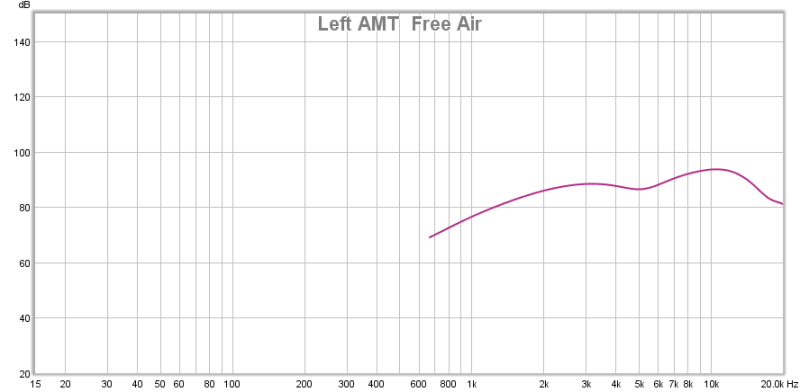
So I think one needs to avoid the back wave from reflecting off any nearby surface behind it - this seem to cause a kind of comb-filter of reinforcement and cancellation.
I am going to try to build a chamber for the AMTPRO-4 that will absorb as much of the back wave as practical, something like this-
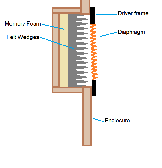
I think ideally it would a long, terminated tapered transmission line- like the "nautilus" design that B&W uses for tweeters (and midranges in some fancy designs.) But I don't know if that's practical in my speaker, so I am just going to try to make the chamber be the best absorber of treble I can come up with. To that end I've bough a bunch of 1/2 inch thick grade F13 felt and a slab of 20 durometer viscoelsastic foam with which to line my chamber, and I've developed a way to make a stack of wedges from the felt.
Experimenting now with the Dayton AMTPRO-4 tweeter. Here's how REW sees the AMTPRO-4 frequency response when the back of the tweeter is closed off by a flat plate (the AMTPRO-4 comes with a felt pad at it's back, that felt pad was retained in this measurement, but the tweeter itself is placed on a flat steel plate and sticks there by dint of the strong magnets in the back.)
Here's how REW saw the frequency response when I hung the tweeter in the middle of a large room so I was measuring the on-axis response "in free air."
So I think one needs to avoid the back wave from reflecting off any nearby surface behind it - this seem to cause a kind of comb-filter of reinforcement and cancellation.
I am going to try to build a chamber for the AMTPRO-4 that will absorb as much of the back wave as practical, something like this-
I think ideally it would a long, terminated tapered transmission line- like the "nautilus" design that B&W uses for tweeters (and midranges in some fancy designs.) But I don't know if that's practical in my speaker, so I am just going to try to make the chamber be the best absorber of treble I can come up with. To that end I've bough a bunch of 1/2 inch thick grade F13 felt and a slab of 20 durometer viscoelsastic foam with which to line my chamber, and I've developed a way to make a stack of wedges from the felt.
Last edited:
AMT testing / amplifier selection
I built rear chambers for the Dayton AMTPRO-4 tweeters, small wooden boxes open on one side; I stacked sheets of 1/2" grade F-13 soft felt to fill the chamber.

The chambers have mounting screws that hold them down onto foam "gaskets" on the rear of the baffles, making a reasonably airtight seal.

This provided a decent mounting for the chambers, which I think can reasonably be expected to absorb the rear output of the drivers without too much in the way of energy reflected back out.
The AMTs are mounted, but I have not yet got rabbets cut into the baffle to flush-mount them. Their response will be a bit less smooth with them surface mounted; flush mounting them will wait till later. The surface mounted AMTs will be OK for testing and so on.

I started off with this small tube amp- at about 1.5 watts - it was enough for the Fountek ribbons tweeters but it proved insufficient to drive the AMT's.
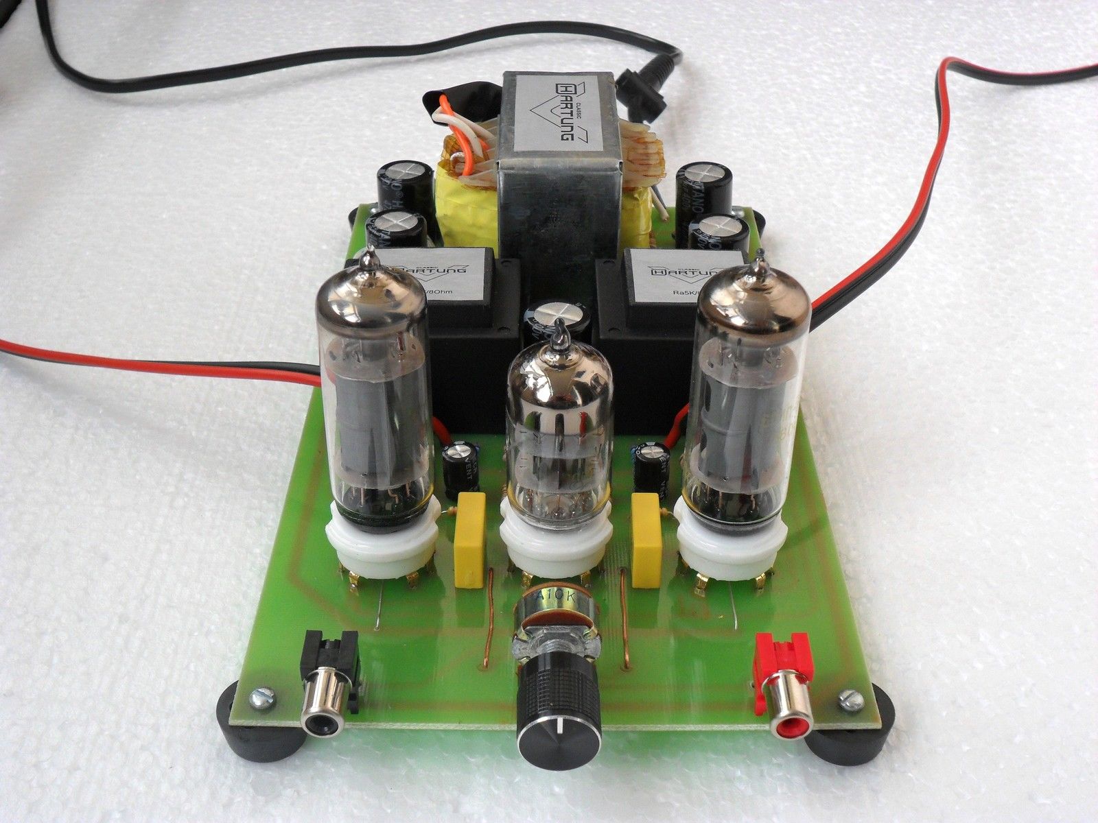
I built this little 10 watt @ 4 ohms Pass DIY "Zen" amp... built with some nice capacitors and so on....

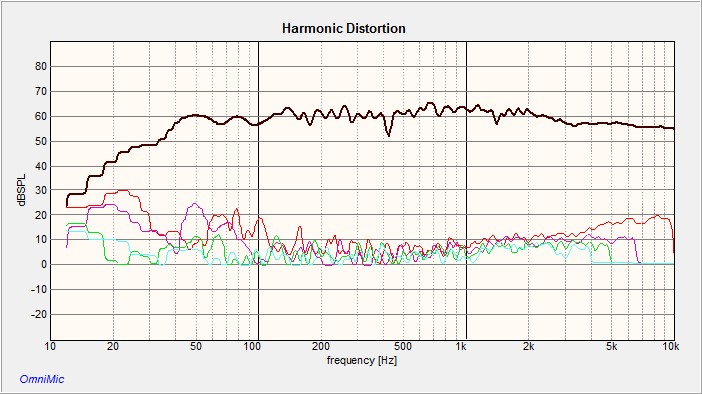
But this had a high level of 2nd harmonic distortion, this curve was taken at about 0.1 watts output, and the level is about 80 dB not 55 dB, this graph was run without proper SPL level calibration. 2nd harmonic is in RED.

So I abandoned the little Zen class A amp and tried an AMC CVT-2030 amp I had laying around, this is a class-A MOSFET-EL34 hybrid amp with about 30 watts output. You can see here that the 2nd harmonic THD exhibited by the little Zen amp has all but disappeared. The level here is about 90 dB.

This is the AMC CVT-2030 amp

The CVT-2030 is a nice amp but too big and heavy to incorporate into the electronics chassis that I am building for this biamp project. So, I am looking into other candidates- I am thinking maybe a TPA3116 amplifier.
SOUND QUALITY
With the CVT-2030 amp, the sound quality is quite good. More tweaking is needed with the MiniDSP's EQ and possibly adding some delay to the tweeter, but the AMTPRO-4 has a very 'dynamic' sound and works quite well down to the 1500 Hz crossover point I used here. I will try a bit lower crossover, 1,000 Hz or maybe even 900 Hz, which will avoid the small wrinkle in the response of the Satori woofer caused by a surround resonance just above 1,000 Hz. I'll report more as this project proceeds.
PS- sorry for the big images- I don't know how to control image size with this forum's editor.
I built rear chambers for the Dayton AMTPRO-4 tweeters, small wooden boxes open on one side; I stacked sheets of 1/2" grade F-13 soft felt to fill the chamber.
The chambers have mounting screws that hold them down onto foam "gaskets" on the rear of the baffles, making a reasonably airtight seal.
This provided a decent mounting for the chambers, which I think can reasonably be expected to absorb the rear output of the drivers without too much in the way of energy reflected back out.
The AMTs are mounted, but I have not yet got rabbets cut into the baffle to flush-mount them. Their response will be a bit less smooth with them surface mounted; flush mounting them will wait till later. The surface mounted AMTs will be OK for testing and so on.
I started off with this small tube amp- at about 1.5 watts - it was enough for the Fountek ribbons tweeters but it proved insufficient to drive the AMT's.
I built this little 10 watt @ 4 ohms Pass DIY "Zen" amp... built with some nice capacitors and so on....
But this had a high level of 2nd harmonic distortion, this curve was taken at about 0.1 watts output, and the level is about 80 dB not 55 dB, this graph was run without proper SPL level calibration. 2nd harmonic is in RED.
So I abandoned the little Zen class A amp and tried an AMC CVT-2030 amp I had laying around, this is a class-A MOSFET-EL34 hybrid amp with about 30 watts output. You can see here that the 2nd harmonic THD exhibited by the little Zen amp has all but disappeared. The level here is about 90 dB.
This is the AMC CVT-2030 amp
The CVT-2030 is a nice amp but too big and heavy to incorporate into the electronics chassis that I am building for this biamp project. So, I am looking into other candidates- I am thinking maybe a TPA3116 amplifier.
SOUND QUALITY
With the CVT-2030 amp, the sound quality is quite good. More tweaking is needed with the MiniDSP's EQ and possibly adding some delay to the tweeter, but the AMTPRO-4 has a very 'dynamic' sound and works quite well down to the 1500 Hz crossover point I used here. I will try a bit lower crossover, 1,000 Hz or maybe even 900 Hz, which will avoid the small wrinkle in the response of the Satori woofer caused by a surround resonance just above 1,000 Hz. I'll report more as this project proceeds.
PS- sorry for the big images- I don't know how to control image size with this forum's editor.
Last edited:
Great job. I think you will be pleased with what the Satori can offer. Add a sub, relieving it of pushing major air and it can present an incredible amount of detail and should match well with the tweeter.
What is the wiggle at ~180Hz? Floor bounce? Lovely looking drivers 😉
Yeah the mic is about a meter away so there's various kinds of room effects below a certain point. When I want to look at the bass response of the speaker itself, I mic close-up.
These will be used in my bedroom, replacing a very nice set of Red Rose Classic Ribbons that I want to sell. The Red Rose's are just 'too much' in that small-ish room. And besides I just have too many speakers- and commerically made ones can be sold, Its much harder to sell DIY, no matter how good.
I won't be using these with a sub, at modest levels the Satoris are just fine, especially in a small room. Rather surprising low bass, actually. These are vented boxes, but I have some rubber stoppers sized to fit the port tubes; I want to experiment with placement and sealed / ported once they're in the other room. I tend to like the "texture" and transient response / lower group delay of sealed boxes, but I tried to tune this enclosure for best Q rather than just for deepest F3. I have to see what sounds best in their final location.
I will be building stands as well, out of maple to match the veneer on the Parts Express cabinets.
I am also going to work out some nice cosmetics for the casework of the electronic chassis. I like to start with a standard Par-Metal chassis and then use a custom machined front panel, and add some exotic wood accents, like THIS Beta-22 headphone amp I built.
Be a while before I get this all finished, and I'll probably be doing minor tweaking on the MiniDSP EQ for years to come....
Nice work! Try a tapered "dagger" shaped (tall 4 sided pyramid) sealed TL behind the AMT, stuffed with foam at the tip and fiberglass or poly fill rest of line - works well to absorb back reflection. If will make all those back wave reflections go away. A flat layer of felt and foam on a flat back wall will still have reflections. Also, try the TPA3116D2 amp with the miniDSP. You get 40 clean watts with 19v laptop brick and less than 0.1% THD. Works great with bi amp.
Yes a tapered back-chamber would have been best, like the closed transmission lines that B&W uses behind their tweeters. Wasn't possible in my cabinet.
Above the back wall of the chamber is a convex piece of viscoelastic urethane, embedded in the felt; the idea being any sound that makes it through the felt to reach the foam layer will be reflected towards the walls and not back through the driver. And sound impinging on the viscoelastic foam- which is quite dense- can't easily propagate through the foam and reflect off the flat back of the chamber. Something like this...

And, yes, I have bought a TPA3116D2 although I will be using it with a linear regulated supply instead of a power brick.
Above the back wall of the chamber is a convex piece of viscoelastic urethane, embedded in the felt; the idea being any sound that makes it through the felt to reach the foam layer will be reflected towards the walls and not back through the driver. And sound impinging on the viscoelastic foam- which is quite dense- can't easily propagate through the foam and reflect off the flat back of the chamber. Something like this...
And, yes, I have bought a TPA3116D2 although I will be using it with a linear regulated supply instead of a power brick.
Last edited:
Working with the system a little while today. Played with the parametric EQ in the MiniDSP, getting some OK looking curves but more work needs to be done. Distortion is quite low from the AMT, as you can see by the red (2nd harmonic) and other colors down below the frequency response curve. There are some wrinkles due to room effects and also, since I haven't flush-mounted the tweeters yet, some treble wrinkles too.
1,500 Hz 48 dB/octave L-R crossover; ignore the SPL figures shown, this is at an average level of 90 dB @ 1 meter, NOT 50 dB as shown.

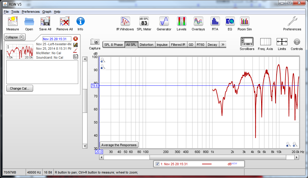
I am a bit confused by the differing curves I am getting from the FREQUENCY RESPONSE and DISTORTION measurement tools in OmniMic. Both use sine sweeps; the FREQUENCY RESPONSE tool has multiple short (~1 sec) 20-20 kHz sweeps, while the DISTORTION tool has ~3 second 20-20 kHz sweeps. The FR curves that result from these tests look totally different. The FREQUENCY RESPONSE test shows a 15 dB peak from about 300 Hz to 1200 Hz, while the DISTORTION FR curve looks OK - like the one above. I'll have to dig around a little more in OmniMic to see if there is some "windowing" adjustments in there that might account for the difference.
1,500 Hz 48 dB/octave L-R crossover; ignore the SPL figures shown, this is at an average level of 90 dB @ 1 meter, NOT 50 dB as shown.
I am a bit confused by the differing curves I am getting from the FREQUENCY RESPONSE and DISTORTION measurement tools in OmniMic. Both use sine sweeps; the FREQUENCY RESPONSE tool has multiple short (~1 sec) 20-20 kHz sweeps, while the DISTORTION tool has ~3 second 20-20 kHz sweeps. The FR curves that result from these tests look totally different. The FREQUENCY RESPONSE test shows a 15 dB peak from about 300 Hz to 1200 Hz, while the DISTORTION FR curve looks OK - like the one above. I'll have to dig around a little more in OmniMic to see if there is some "windowing" adjustments in there that might account for the difference.
Last edited:
Now that I've got drivers that I like, and amplifiers to drive them, I've spent a little time fiddling with crossover frequencies- and it seems that with this AMTPRO-4 and the Satori a 1500 Hz crossover works well. I may revise that later, but that's where I am at right now.
So- next is building the electronics all into a handsome chassis; that will take quite a while, and is one of the parts of DIY I like best.
There is also the matter of EQ. The MiniDSP offers capacity for quite a lot of parametric EQ. There's six "per channel" [i.e., LEFT and RIGHT] parametirc EQ points, PLUS six "per driver" [Left woofer, left tweeter; right woofer, right tweeter] parametirc EQ's. This pair of drivers isn't perfect (although they are damned good!) and so a little EQ here and there might bring them closer to flat response; and certainly there's the baffle-step effect, and then on top of that room effects- especially in the bass- that can be improved somewhat.
Setting this kind of complex EQ by ear is an exercise in futility, I have found. Seems to me that using a tool like OmniMic or REW as a guide and then finishing off the final "voicing" based on my ears / my taste might lead to good sound.
I've used OmniMic to check certain things in terms of overall balance and room effects with my other "factory made" speakers, but this is the first time I'm using it in a design-adjustment process. Bit of a learning curve to use it this way- it's immediately obvious to use it to see if tweeter distortion is a problem, or for overall tweeter / woofer amp gain settings. But using it to work out EQ is another matter altogether. I want to use EQ to provide as close a neutral sonic character as I can, but that doesn't mean running a curve and then inserting EQ to flatten every bump. First off, the bumps might be artifacts of one sort or another- room modes, reflections, diffraction effects. You can help minimize the coloration introduced by bass room modes and some driver minor driver resonances using EQ, but trying to EQ out the other effects is going to add MORE coloration to the sound, it seems to me. I guess the answer is to run lots of curves, spatial plots as well as 2-d plots, in an effort to sort out the various room effects from the driver behavior, and then try to use judicious amounts of EQ to deal with the actual speaker coloration.
I tried using REW and it has some interesting features, but I have yet to get it to calculate any sensible filters. The eq files it creates- which the MiniDSP is supposed to use to calculate filter biquads- don't seem to work. Importing REW EQ files into the MiniDSP results in a biquad error from the MiniDSP. And setting the gain, Q and frequency manually based on calculations done by REW has not resulted in good sound.... likely due to the lack of decent measurement quality. I'll work some more with this, I think there's a fair amount of user error in my use of REW at this point.
So here are some more curves from OmniMic....
After doing a few measurements from my listening position and then trying some mild manual EQ today, I got this....
Ignore the magnitude figures- this is about 85 dB SPL not 45- here is my curve with "combination" of a short integration window for the treble along with longer window interval for the bass- one-twelfth octave smoothing:

Same data with 1/3 octave smoothing- I think this is closer to what one hears, I don't think that small (+/- 5 dB) highish-Q peaks indicate what I hear.

This actually sounded too "midrangey" - a bit of a "honk" or "squawk" character to the sound. I'm going to run more curves including some sactial plots and see if I can refine things further...
One thing I have to say- things are now sounding closer and closer to what I expected here- the satori woofer is providing very good sound, quite detailed, and the bass extension is quite good. Using EQ to take out some of the room mode energy gave me better sounding bass- much less a "one note bass" now that I have taken some of the energy around 50 Hz out, which is my main room mode.
Interestingly, this 2-D plot shows a fairly steep rolloff above 10 kHz- but the speakers do NOT sound like they lack treble. Now, it's true I can't hear much above 16 kHz any more due to my age, but still I'd certainly be able to hear a 10-db-per-octave rolloff above 10 kHz. I think that doing several measurements at multiple locations then averaging them would give me a better picture of the actual treble behavior.
I'm glad I'm using DSP fro my crossover, trying to optimize magnitude AND phase while trying to build an analog crossover seems like it would be next to impossible for me....
So- next is building the electronics all into a handsome chassis; that will take quite a while, and is one of the parts of DIY I like best.
There is also the matter of EQ. The MiniDSP offers capacity for quite a lot of parametric EQ. There's six "per channel" [i.e., LEFT and RIGHT] parametirc EQ points, PLUS six "per driver" [Left woofer, left tweeter; right woofer, right tweeter] parametirc EQ's. This pair of drivers isn't perfect (although they are damned good!) and so a little EQ here and there might bring them closer to flat response; and certainly there's the baffle-step effect, and then on top of that room effects- especially in the bass- that can be improved somewhat.
Setting this kind of complex EQ by ear is an exercise in futility, I have found. Seems to me that using a tool like OmniMic or REW as a guide and then finishing off the final "voicing" based on my ears / my taste might lead to good sound.
I've used OmniMic to check certain things in terms of overall balance and room effects with my other "factory made" speakers, but this is the first time I'm using it in a design-adjustment process. Bit of a learning curve to use it this way- it's immediately obvious to use it to see if tweeter distortion is a problem, or for overall tweeter / woofer amp gain settings. But using it to work out EQ is another matter altogether. I want to use EQ to provide as close a neutral sonic character as I can, but that doesn't mean running a curve and then inserting EQ to flatten every bump. First off, the bumps might be artifacts of one sort or another- room modes, reflections, diffraction effects. You can help minimize the coloration introduced by bass room modes and some driver minor driver resonances using EQ, but trying to EQ out the other effects is going to add MORE coloration to the sound, it seems to me. I guess the answer is to run lots of curves, spatial plots as well as 2-d plots, in an effort to sort out the various room effects from the driver behavior, and then try to use judicious amounts of EQ to deal with the actual speaker coloration.
I tried using REW and it has some interesting features, but I have yet to get it to calculate any sensible filters. The eq files it creates- which the MiniDSP is supposed to use to calculate filter biquads- don't seem to work. Importing REW EQ files into the MiniDSP results in a biquad error from the MiniDSP. And setting the gain, Q and frequency manually based on calculations done by REW has not resulted in good sound.... likely due to the lack of decent measurement quality. I'll work some more with this, I think there's a fair amount of user error in my use of REW at this point.
So here are some more curves from OmniMic....
After doing a few measurements from my listening position and then trying some mild manual EQ today, I got this....
Ignore the magnitude figures- this is about 85 dB SPL not 45- here is my curve with "combination" of a short integration window for the treble along with longer window interval for the bass- one-twelfth octave smoothing:
Same data with 1/3 octave smoothing- I think this is closer to what one hears, I don't think that small (+/- 5 dB) highish-Q peaks indicate what I hear.
This actually sounded too "midrangey" - a bit of a "honk" or "squawk" character to the sound. I'm going to run more curves including some sactial plots and see if I can refine things further...
One thing I have to say- things are now sounding closer and closer to what I expected here- the satori woofer is providing very good sound, quite detailed, and the bass extension is quite good. Using EQ to take out some of the room mode energy gave me better sounding bass- much less a "one note bass" now that I have taken some of the energy around 50 Hz out, which is my main room mode.
Interestingly, this 2-D plot shows a fairly steep rolloff above 10 kHz- but the speakers do NOT sound like they lack treble. Now, it's true I can't hear much above 16 kHz any more due to my age, but still I'd certainly be able to hear a 10-db-per-octave rolloff above 10 kHz. I think that doing several measurements at multiple locations then averaging them would give me a better picture of the actual treble behavior.
I'm glad I'm using DSP fro my crossover, trying to optimize magnitude AND phase while trying to build an analog crossover seems like it would be next to impossible for me....
Last edited:
After running curves and applying EQ with mixed results, I did a little more research and re-read some advice that Rick Caig of Sleah Audio gave me- he said to use a shelf filter in the MiniDSP to compensate for baffle step loss. I had given this some thought and had the idea that baffle-step effects would be showing up in my measurements and so in applying the various PEQ filters I was setting I would be compensating for baffle step as well as other artifacts of speaker sound reproduction. I think that this may be true in fact, but the problems are getting a clean enough measurement and then getting the right filter function by trial-and-error.
So, I did a little reading and - lo and behold!- the folks at MiniDSP have some good advice see Stereo 2 Way Xover
This discussion includes this diagram:

HAHAHA I actually - finally- read the manual! RTFM is something alien to me, generally speaking- and this is not to my credit.
Anyway, using the baffle-step calculator in Jeff Bagby's Excel sheet at http://audio.claub.net/software/FRD_Blender/FRD%20Response%20Blender%202.0.xls and I got this curve:

I hadn't thought to use a shelf-type EQ up to this point, but I followed Rick Caig's advice- and the advice from the application note from the MiniDSP site, and used a high shelf to add gain in the region of baffle-step loss. I also added a little PEQ right at the ~1 kHz peak shown by the simulation.
Here's the resulting in-room response I got from a quick run -

This sounded COMPLETELY different from my earlier efforts- much more natural and realistic. There's still some work to do with speaker placement and maybe a little EQ to flatten the low end, and of course a one-point in-room response isn't a true picture of the top octaves, but the result of following this good advice about using a shelf filter for baffle step yielded the best sound so far.
So, I did a little reading and - lo and behold!- the folks at MiniDSP have some good advice see Stereo 2 Way Xover
This discussion includes this diagram:
HAHAHA I actually - finally- read the manual! RTFM is something alien to me, generally speaking- and this is not to my credit.
Anyway, using the baffle-step calculator in Jeff Bagby's Excel sheet at http://audio.claub.net/software/FRD_Blender/FRD%20Response%20Blender%202.0.xls and I got this curve:
I hadn't thought to use a shelf-type EQ up to this point, but I followed Rick Caig's advice- and the advice from the application note from the MiniDSP site, and used a high shelf to add gain in the region of baffle-step loss. I also added a little PEQ right at the ~1 kHz peak shown by the simulation.
Here's the resulting in-room response I got from a quick run -
This sounded COMPLETELY different from my earlier efforts- much more natural and realistic. There's still some work to do with speaker placement and maybe a little EQ to flatten the low end, and of course a one-point in-room response isn't a true picture of the top octaves, but the result of following this good advice about using a shelf filter for baffle step yielded the best sound so far.
I have a DEQX that I use with a pair of Magneplanar MG-3.6's. I decided to try using the DEQX to measure the Satori woofer / Dayton AMTPRO-4 drivers in my enclosure.
Here's what I got. The baffle diffraction step response of the woofer is different than the simulation. Woofer in pink; tweeter in brown. Note this is with smoothing set to a low value and a window that limits accuracy to 100 Hz or so.

Quite interesting. I'm going to try using this graph as a basis for a set of EQ, at least in terms of the baffle step and crossover region.
Here's what I got. The baffle diffraction step response of the woofer is different than the simulation. Woofer in pink; tweeter in brown. Note this is with smoothing set to a low value and a window that limits accuracy to 100 Hz or so.
Quite interesting. I'm going to try using this graph as a basis for a set of EQ, at least in terms of the baffle step and crossover region.
Last edited:
Using the DEQX FR plot gave me a better starting point than either the calculated baffle-step plot or plots made using OmniMic or REW. (I wish I could use a DEQX for this speaker instead of the MiniDSP but financial sanity prevents this....) - the software in the DEQX is really fantastic.
Using the DEQX plot, I came up with a really good sounding EQ regime- the best, most balanced so far. These drivers are really little short of amazing. The AMT's, in particular, give a really realistic presentation, and the Satori woofer offers much better bass extension than any similar driver I've used, as well as very low coloration over the range I'm using it in.
Here's a group delay plot from the DEQX of the drivers / enclosure - you can see the rise in group delay at the bottom of the range typical of vented enclosures- but between my design and the great Satori driver, the increase of group delay is only about 7% at 40 Hz, and about 15% at 30 Hz, meaning the bass "texture" of this woofer alignment ought to be quite good.

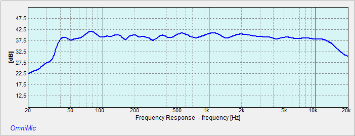
And here's an in-room OmniMic FR plot of the EQ results using the DEQX FR curve as a starting point. HF rolloff about 15 kHz may be an artifact of mic placement, or it may be real- I can't tell as I can't hear up that high. This is 1/6 octave smoothing, with a "spliced curve" below about 500 Hz - bass curve with a longer impulse window than the treble part. It's about +/- 2 dB from 40 Hz to 15 kHz.
Using the DEQX plot, I came up with a really good sounding EQ regime- the best, most balanced so far. These drivers are really little short of amazing. The AMT's, in particular, give a really realistic presentation, and the Satori woofer offers much better bass extension than any similar driver I've used, as well as very low coloration over the range I'm using it in.
Here's a group delay plot from the DEQX of the drivers / enclosure - you can see the rise in group delay at the bottom of the range typical of vented enclosures- but between my design and the great Satori driver, the increase of group delay is only about 7% at 40 Hz, and about 15% at 30 Hz, meaning the bass "texture" of this woofer alignment ought to be quite good.
And here's an in-room OmniMic FR plot of the EQ results using the DEQX FR curve as a starting point. HF rolloff about 15 kHz may be an artifact of mic placement, or it may be real- I can't tell as I can't hear up that high. This is 1/6 octave smoothing, with a "spliced curve" below about 500 Hz - bass curve with a longer impulse window than the treble part. It's about +/- 2 dB from 40 Hz to 15 kHz.
Why do you think the DEQX is showing you something REW cannot? Is is not just a matter of changing the gating in REW? Looks good BTw, the Satori is excellent.
I changed the gating in REW to match the gating I set in DEQX and the REW curve did not look like the DEQX curve, lots more artifact in the REW curve. Can't explain why.
Interesting. It looks as though REwbis actually giving you more information and the DEQX is somehow smoothing the LF response. I would expect all the humps and bumps due to room modes and such.
Quick update: I am REALLY liking this Dayton AMTPRO-4. Once decently balanced with the Satori woofer, I am appreciating it's very transparent sound- really really good. Using a TPA3116- based class D amp to drive the AMT's, this works very well. Just the right amount of power.
The Satori is no slouch, either, it has really low distortion and amazing bass extension for such a small driver. A great match with the AMT.
You could build a 2-way speaker with these two drivers and a passive crossover, I'm sure, but certainly I couldn't do so. The only way possible for me was to use the DSP approach, which let me fiddle around with the crossover point, slopes, etc.-
Update
I tried to use a router to flush-mount the AMTPRO-4 tweeters in the baffles of the Dayton enclosures, and botched the job. So I paid a local craftsman to do it and to show me how it's done. He made a template using scrap wood, and has a actaul router, whereas I was trying to use my Dremel TRIO tool, which is a handy tool but not good for this kind of thing. Anyway I bought new baffles and he flush mounted the tweeters. Flush mounting tweeters gives a little flatter frequency response and a little better directional characteristics. See Flush mounting tweeters a good discussion of this. Every little bit helps.
I am now building all the electronics into a Par-Metal 20-16123B chassis, because I want all the electronics to be in a single unified unit. I took apart the Topping TP-60 amp, removed the volume control pot and the input selector relay. The rear panel of the TP-60 lent itself to re-use, so I mounted it on the back of the Par-Metal case. I replaced the standard IEC AC inlet socket of the TP-60 with an IEC inlet with a line filter- I want to try and make sure that the RF noise generated by these switching amps doesn't get out into the environment, especially onto the power line. I am using one pair of the RCA jacks on the back of TP-60 panel for my analog inputs, although I imagine that this setup will mostly be used with digital audio brought in through the Windows 8 tablet that is part of the setup.
Here's what the rear panel of the Par-Metal case looks like; the various components are all laid out in the chassis but not fixed in place or wired at this point.
It's been a while since I've posted regarding this project. The building phase is done and now I am working on the settings- with the DSP crossover there's quite a lot to fiddle with. Crossover points, slopes, per-driver EQ, overall EQ, per-driver time delay....
ANYWAY here are some pictures
The speakers look like this
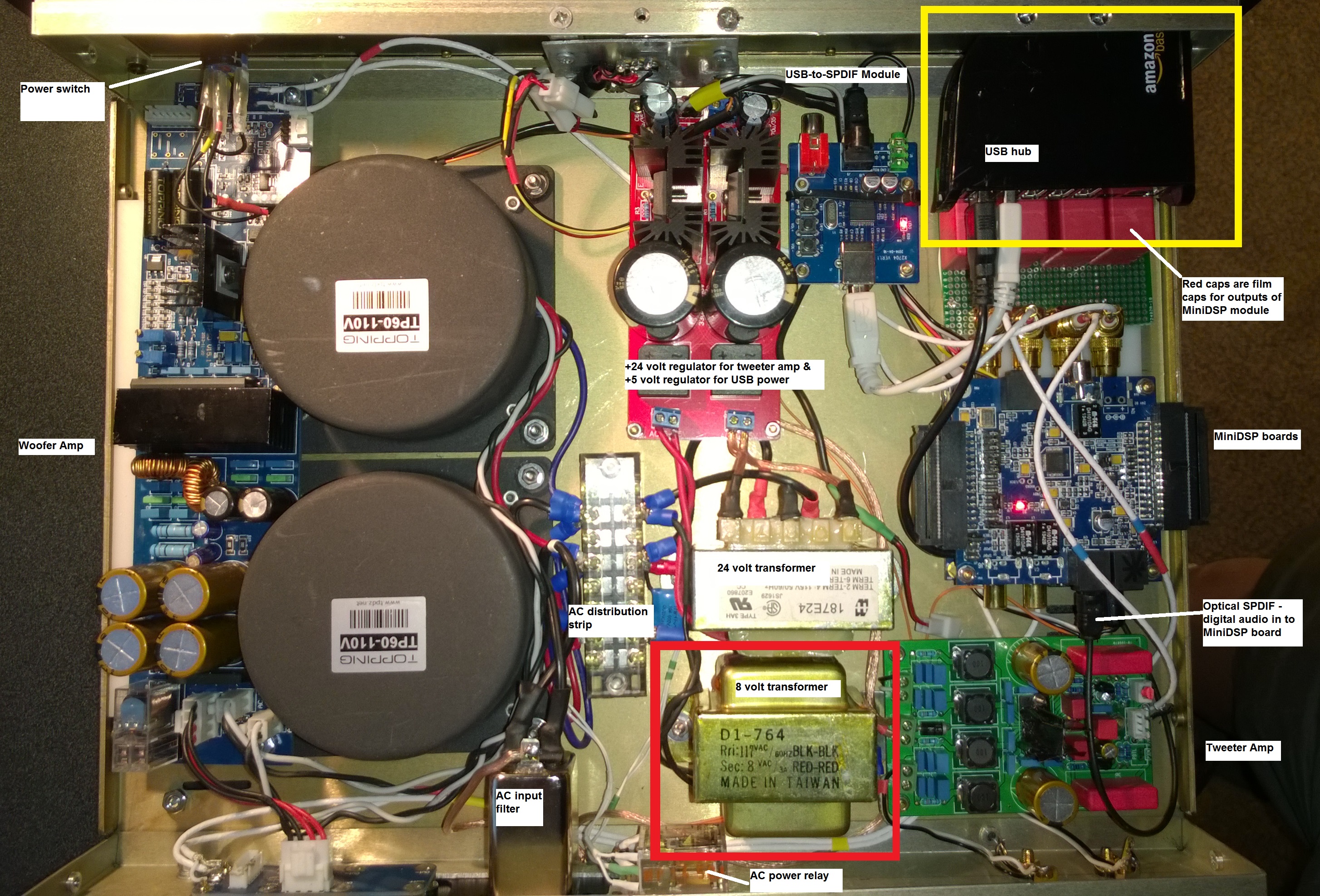
Here's the electronics chassis with labels to identify what's going on inside
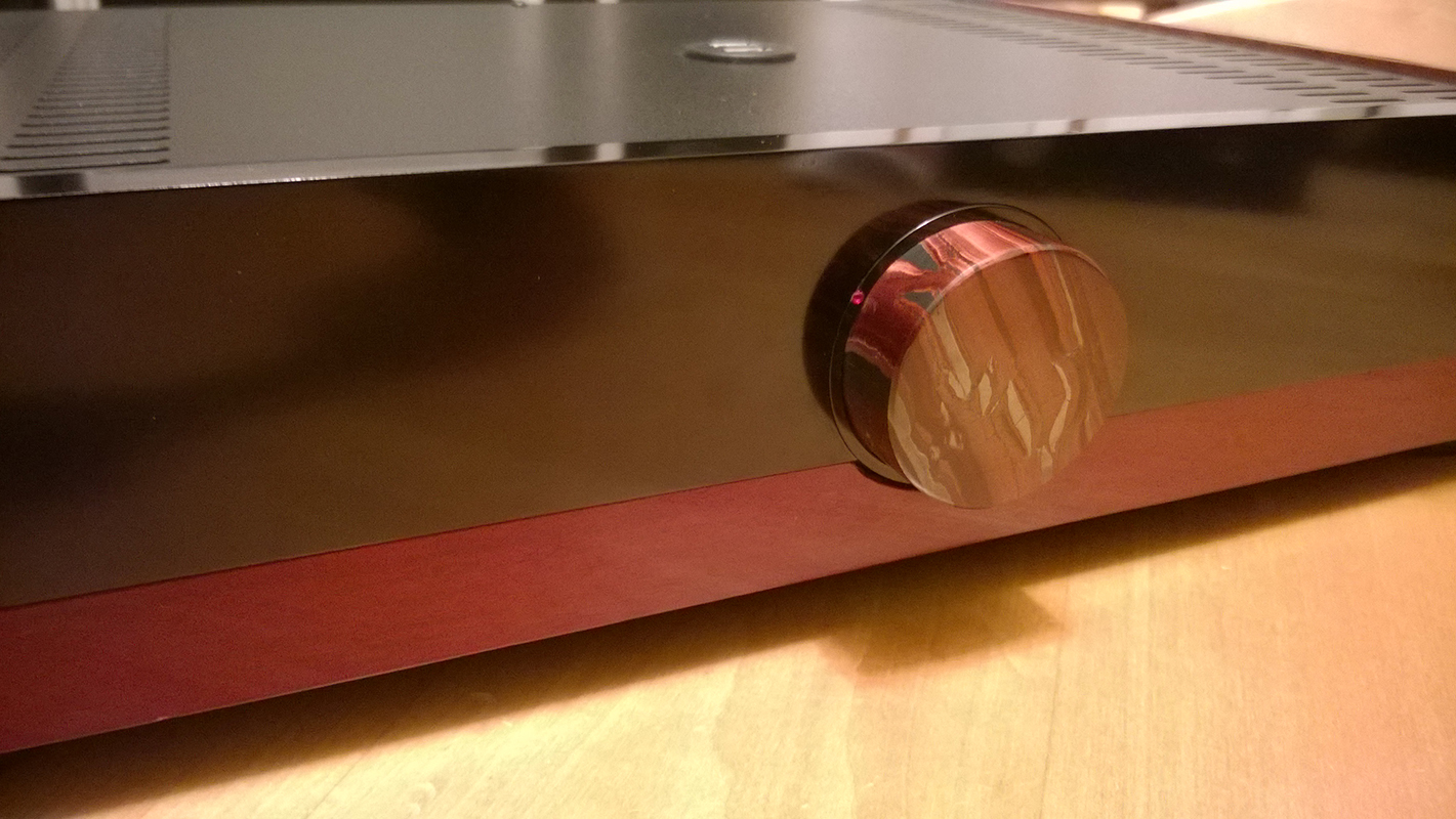
Here's the front panel with the knob which was ground of out red tigers eye stone; a static photo doesn't do this chatoyant mineral justice.
Here is a side view of the chassis; the wood is bloodwood.

A profile view, with the speakers in the background

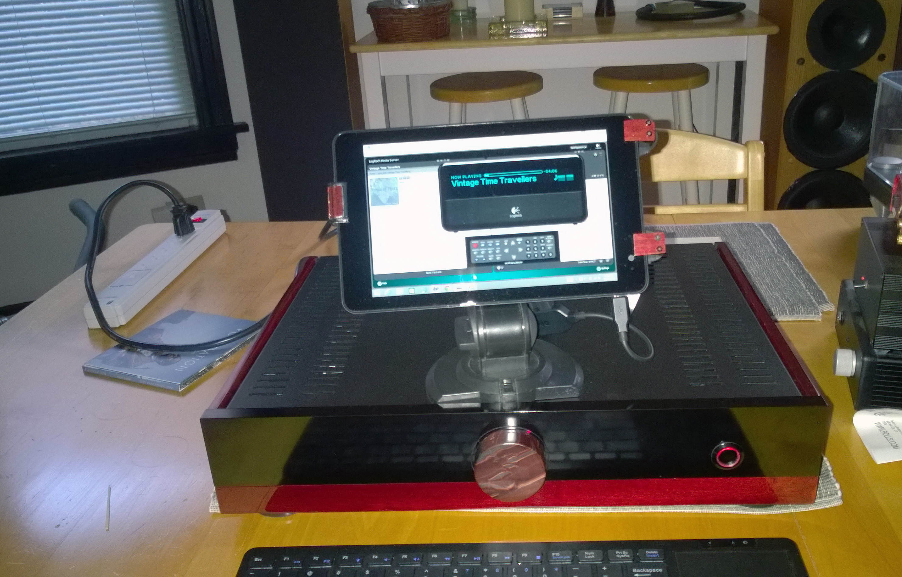
And here is the chassis with the tablet perched on top, the tablet is the "player" playing flac files from my server; it's also the control interface for the DSP.
(those speakers in the background are another project- "Long Road" 3-way active speaker
And how the hell do you set the image size in this editor? This is ridiculous.
ANYWAY here are some pictures
The speakers look like this
An externally hosted image should be here but it was not working when we last tested it.
Here's the electronics chassis with labels to identify what's going on inside
Here's the front panel with the knob which was ground of out red tigers eye stone; a static photo doesn't do this chatoyant mineral justice.
Here is a side view of the chassis; the wood is bloodwood.
A profile view, with the speakers in the background
And here is the chassis with the tablet perched on top, the tablet is the "player" playing flac files from my server; it's also the control interface for the DSP.
(those speakers in the background are another project- "Long Road" 3-way active speaker
And how the hell do you set the image size in this editor? This is ridiculous.
- Status
- Not open for further replies.
- Home
- Loudspeakers
- Multi-Way
- A build: 2-way, biamp, integrated source....