Andy: A few more things that you could try.
1. Put an EMI_EMC filter between the AC mains and whichever power supply you are using (SMPS or non-SMPS). Together with the isolation transformer, this should reduce whatever noise is being injected into the local AC mains. Ideally you'd design or build your own EMI_EMC filter, but ready-made filters are better than nothing.
3. Put an EMI_EMC filter between the AC mains and your line preamp to reduce the amount of noise that can get into the preamp.
After searching on the Net, I gave up trying to find a design for an EMI filter ... but I did find Fuseco.com.au which sells Schaffner 2090 general purpose RFI filters. A 1a one costs $15 + GST ... so (as they had a minimum non-account customer order of $50) I bought 4!
")
So this will be enough for:
* the SMPSU,
* my preamp, and
* one each for my (mono) active XOs.
And I didn't break the bank!
So thanks again, Jonathan
Andy
Hi Andy. Whilst driving to the supermarket I remembered this. Maybe it can work?
Finesse Voltage Regulator Noise!
Then I thought of a simple capacitance multiplier. It might loose 2 V, you might be OK to loose a little more. Even loosing 1 V should start to work depending on the peak to peak noise level if a single transistor. Keep it simple is my advice. If the transistor is reasonably fast and cap of good quality it can work. Residuals seem always to look nice also. You might be best to use a film cap.
Capacitance Multiplier Power Supply Filter
These ideas are so cheap as to say why not try. If someone already did sorry.
Hi Nigel. Long time no see! I hope that you are doing well.
Most capacitance multipliers (including the ESP design) are designed for use with AC mains-frequency rectification and linear amplifiers, while Andy seems to want to use the SMPS. Since the harmonics from an SMPS extend to much higher frequencies (well over 1MHz), it is questionable whether an active or passive filter designed to address AC mains-frequency rectification will remain effective for SMPS.
The primary causes are passive component parasitics and active device capacitances allowing various leakage paths for the higher noise frequencies, and if high currents are involved, too-big loop areas and_or inadequate shielding.
OTOH, modern SMPS (should) have their switching fundamentals above 20kHz, more likely above 40~50kHz, so there should no need to address lower frequencies (unless some kind of IMD is occurring). The high switching frequencies will allow the use of smaller component values which will be of smaller physical size, and this may allow the parasitics to be kept small enough to cope with the SMPS harmonics.
Having designed and built a multitude of both passive and active power filters, my recommendation would be for Andy to first consider a passive solution, because an active filter introduces additional issues.
First and foremost, the pass device (BJT or MOSFET) in an active filter will have its own capacitances which allow HF noise to leak from input to output (above and beyond the parasitics of the passive components used to set the filtering), and this may make an active filter less suitable for use with SMPS harmonics than with AC mains-frequency rectification. OTOH, active devices put much less current through the passive components of the filter, which should allow the use of small capacitances (film capacitors, for example) and high resistance_inductive values, but this needs to be thought about and incorporated into the design.
The values given for the ESP capacitance multiplier clearly require electrolytics, although with the Darlington pass devices it should be possible to increase the 220ohm series resistors and reduce the 470uF capacitors (or use MOSFETs rather than Darlingtons).
Other issues include, for stability reasons it may not be advisable to use as high of a filter order for an active filter as for a passive filter; using too large of an capacitance on the output of the active filter may destroy the pass device (particularly on power-up); the pass device will need to be generously-sized and mounted on a heatsink, etc. etc.
IMO Andy has a better chance of succeeding with passive filtering of his SMPS than with active filtering, but whatever he does, his results should be interesting.
I agree that Andy should try his best to borrow a spectrum analyzer (some digital oscilloscopes have FFT capabilities built-in) and take before-and-after measurements. Understanding the relationship between measurements and what his ears are telling him is always useful, even more so should Andy wish to consider similar or more elaborate solutions in the future.
One other possible avenue would be for Andy to look for an SMPS that is based on soft-switching technology, as these should generate significantly reduced HF harmonics. Probably still too much hash for use in an MC headamp or high-gain phono equalizer, but most likely acceptable for line preamps, power amplifiers, and turntable motors.
hth, jonathan
After searching on the Net, I gave up trying to find a design for an EMI filter
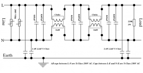
Andy, perhaps something like could do (I haven't simulated it to see what the attenuation characteristics are like).
hth, jonathan
Attachments
Hi Jonathan. My feeling it it is worth a try. If the transistor is very fast and a good cap it might surprise us. BD139 might be OK. It certainly could work with the 80 kHz if that's what is used. Pulling the fundamental away reduces the problem and my guess is the first MHz is in the bag. It would help to have an analyzer. By accident I did this with the Hypex SMPS. I sent it's auxiliary output into simple transistor amplified zener with capacitor filtering ( BC327/337). Space did not permit more. It works far better than expected. I was a little surprised the output was so raw. Remember I wasn't at this stage thinking I had cured the problem. Compared with the raw Hypex graphs I had done well. See how the effectiveness is reduced at 5 MHz. Still not bad and sounded excellent. These graphs were not designed for showing and just my notes to me. The bad stuff is bad and is intended as a high quality PSU. I am not displeased. I just feel it asks a bit much to think all will know this. Hum is superb. These zeners were just using 10 uF high grade electrolytic like Panasonic FC . Scope to do better.
My suspicion is loosing 3 V might be ideal. It could be Early effect that is in someway reducing the effectiveness when losses are lowered? The final output cap doing a good job, a small resistance to aid it like that in an inductor.
Possibly a common mode choke output? Read carefully the data and look to the > 1 MHz. 10 mH should be ball park. I have a hunch ceramic caps to be useful. NPO might be best?
Simple circuits reduce regulator noise floor | EDN
This came up when researching other circuits today. As he says up to 1 MHz not a problem. Number 1 seems ideal. Tweak resistor to be as high in value as possible. Aim for 3 V loss. As the problem is RF C might be 0.1 uF. The higher the transistor gain the better. Ft also. I would avoid Darlingtons. Complimentary feedback pair worth trying if a scope available.
This came up when researching other circuits today. As he says up to 1 MHz not a problem. Number 1 seems ideal. Tweak resistor to be as high in value as possible. Aim for 3 V loss. As the problem is RF C might be 0.1 uF. The higher the transistor gain the better. Ft also. I would avoid Darlingtons. Complimentary feedback pair worth trying if a scope available.
Hi Nigel: Although I have qualms about how much power (current, and voltage drop) can be put through a TO-92 device (BC327_BC337) or even a TO-126 device (BD139), your measured results look worthy of additional experimentation.
That said, Andy has already given himself more than enough work (verifying the effectiveness of the input EMI filters, or lack of it, and possibly knocking up a few simple pi filters). I recommend that we let him get on with it, and gradually introduce other possibilities if and as his appetite increases.
Regarding Darlingtons vs. CFPs, when distortion is important (power amplifier output stage) I would not hesitate to use CFPs, but for noise filtering duties I would start with Darlingtons.
Darlingtons allow the power input of the master device to be kept separate from the slave device, with the current through the master device perhaps 1_50th of the slave device. These two factors allow the master device to be connected to the power input via an R_C, L_C or L_R_C filter for more effective filtering, while keeping the slave device connected directly to the power input for minimal voltage drop at higher currents.
With CFPs, there is no way to place a high-value capacitor in the collector feed of the master device, since this coincides with the base of the slave device. Hence, although CFPs do offer one Vbe less voltage drop, the master device cannot be filtered to any greater extent than the slave device collector current dictates.
Looking at the following schematic, if T2 is bonded with Dar1 into a CFP, the collector of T2 can no longer be connected to the junction of R3_C4, worsening PSRR.

Associated article here.
DDDAC 1794 NOS DAC - Non Oversampling DAC with PCM1794 - no digital filter - modular design DIY DAC for high resolution audio 192/24 192kHz 24bit
I don't believe that anything (other than a little calculation and work) prevents one from R_C, L_C or L_R_C filtering the Darlington master device power input in the ESP capacitance multiplier article that you linked to.
regards, jonathan
That said, Andy has already given himself more than enough work (verifying the effectiveness of the input EMI filters, or lack of it, and possibly knocking up a few simple pi filters). I recommend that we let him get on with it, and gradually introduce other possibilities if and as his appetite increases.
Regarding Darlingtons vs. CFPs, when distortion is important (power amplifier output stage) I would not hesitate to use CFPs, but for noise filtering duties I would start with Darlingtons.
Darlingtons allow the power input of the master device to be kept separate from the slave device, with the current through the master device perhaps 1_50th of the slave device. These two factors allow the master device to be connected to the power input via an R_C, L_C or L_R_C filter for more effective filtering, while keeping the slave device connected directly to the power input for minimal voltage drop at higher currents.
With CFPs, there is no way to place a high-value capacitor in the collector feed of the master device, since this coincides with the base of the slave device. Hence, although CFPs do offer one Vbe less voltage drop, the master device cannot be filtered to any greater extent than the slave device collector current dictates.
Looking at the following schematic, if T2 is bonded with Dar1 into a CFP, the collector of T2 can no longer be connected to the junction of R3_C4, worsening PSRR.
Associated article here.
DDDAC 1794 NOS DAC - Non Oversampling DAC with PCM1794 - no digital filter - modular design DIY DAC for high resolution audio 192/24 192kHz 24bit
I don't believe that anything (other than a little calculation and work) prevents one from R_C, L_C or L_R_C filtering the Darlington master device power input in the ESP capacitance multiplier article that you linked to.
regards, jonathan
Hi Jonathan.
I just did a TL431 powering an old scrap box MJ3000 verses FQA 55N10 also from the scrap box. The MJ did a good job! As you say the complimentary feedback pair is a good option. So low in distortion as to be almost perfect both for measurements and the ears. I used BD139/140 and some 30 MHz output devices. I have no idea what the combined Ft was but must be 10 MHz? When added to an OP604 they made an amplifer that could run speakers or a power amp. It was not obvoiusly worse than the OPA604. The idea being a preamp that was OK to power my OB speakers if I wanted ( to take them out and about ) . OPA was what I had in the scrap box so could be any decent op amp. NE 5534 did not like this set up. Needs careful C comp adjustement if used. The bias was simple 2 x 1N4007 at first. Shame no one does Cfbp as a device like a Darlington. Don't think I have seen one?
BTW. I did my Cfbp as a dead bug device. The 1N4007 built in. It wasn't bad. The tracking was OK! I feel I gained more by dead bug than lost in bad tracking. I used epoxy to get a thermal bond.
Hi Nigel:
I have been doing some work on 4-stage active power filters, and once again the Cob of the slave device (assuming either Darlington or CFP) dominates the HF filtering performance. Power requirements permitting, a slave device with smaller Cob increases HF attenuation.
Using OnSemi's MJE15034_MJE15035 (TO-220) & NJW0281_NJW0302 (TO-3P), I compared CFP & Darlington for the output stage of the active power filters. Taking advantage of a Darlington's ability to separate master and slave devices, and the low current through the master device, for the Darlington only the master device was powered from a pre-filter.
The results are that from 50Hz to about 25kHz, the CFP has better PSRR. Below 50Hz, and above 25kHz (up to 1MHz, where I stopped), the Darlington showed greater PSRR.
No conclusions, just observations.
regards, jonathan
I just did mine with BD139 + 2SA1962. The results in complimentary feedback pair are dramatic and far out perform an industrial Darlington. We are looking at 16 db at 50 Hz. This should be where speed is not of grater importance. The other nice thing is it behaves as a single NPN transistor in terms of Vbe.
That said, Andy has already given himself more than enough work (verifying the effectiveness of the input EMI filters, or lack of it, and possibly knocking up a few simple pi filters). I recommend that we let him get on with it, and gradually introduce other possibilities if and as his appetite increases.
regards, jonathan
Hah - yes, I do have a lot on my plate, Jonathan!
Have bought 4 Schaffner 2090 general purpose RFI filters and put one (temporarily) in a box with an IEC input plug and 3-pin mains output plug ... so it is easy to put it in and out of circuit in front of a component. Haven't done any testing, yet.
Have also ordered the Nichicons for my pi filter ... they will be delivered in a week or so. Unfortunately, the only place I can find that will sell me 2 x Schurter 0.035mH inductors (instead of 100!) doesn't have them in stock - so it might be several months before I can make up the pi filter.
So cleaning up the output of the SMPSU will have to wait - but at least I can deal with the blocking RFI at the input to other components.
Meanwhile, I will follow with interest what you guys propose.
Regards,
Andy
I suggest winding the 35uH coils yourself - that value is easy to make on an iron dust toroid. Something around 20mm diameter should do.
Here's a very useful resource - Iron Powder Toroidal Cores For Power Conversion and Line Filter Applications : CWS ByteMark, largest supplier of toroids, ferrite cores, iron powder cores, MPP cores and RF cores
Here's a very useful resource - Iron Powder Toroidal Cores For Power Conversion and Line Filter Applications : CWS ByteMark, largest supplier of toroids, ferrite cores, iron powder cores, MPP cores and RF cores
Andy, how about something like a Murata 60A363C, or perhaps two pieces of Murata 60A193C in series? It appears that both Mouser and Digikey have these in stock.
FWIW, you may have better luck locating these small-value inductors if you search for the values in microHenries rather than milliHenries.
Also FWIW, in my own subjective listening evaluations IEC connectors have on occasion lead to variable results. Instead, I would recommend high-pressure connections such as blade-type FastOn connectors, screw terminal strips, crimped-on O-lug or spade-lugs, or soldering.
Abraxalito (I've been following your blog posts with interest), I've wound inductors myself, but not toroidals. Do you have any good links to winding toroidal inductors?
regards, jonathan
FWIW, you may have better luck locating these small-value inductors if you search for the values in microHenries rather than milliHenries.
Also FWIW, in my own subjective listening evaluations IEC connectors have on occasion lead to variable results. Instead, I would recommend high-pressure connections such as blade-type FastOn connectors, screw terminal strips, crimped-on O-lug or spade-lugs, or soldering.
Abraxalito (I've been following your blog posts with interest
), I've wound inductors myself, but not toroidals. Do you have any good links to winding toroidal inductors?regards, jonathan
No, I'm not very hot on winding toroids myself, though I have watched the girls at the local electronics market making them. They have a certain hand tool which pulls the wire through the centre of the core, I must take a closer look next time.
My own method of winding them isn't particularly elegant and I've not gone beyond winding twice my own span (around 3.7m) onto a core. I place the first turn right at the centre of the pre-cut length of wire and wind first one side, then the other (which normally goes over the top of the first side). With about 3.7m of wire I can get up to around 2mH on a sendust core.
Fortunately to wind 35uH, that'll fit on one layer and so shouldn't be too time-consuming.
Glad you're enjoying the blog
Abraxalito, in lieu of a dedicated hand-tool, perhaps you could form both ends of the pre-cut wire into soldered loops, making it easier to apply tension and localizing any insulation or wire damage to the loops.
Do you periodically "tack" your in-progress windings in place with adhesive to keep things from unravelling and maintain tension?
After I wind my inductors, I dip them into high-temperature paraffin to keep the coils from vibrating or moving. I tend to do the same to commercially-made inductors and CM chokes, too.
regards, jonathan
I've not noticed any problems with maintaining tension but then again its not really a problem in my applications when the windings 'sag' a little, after all so far they're only for my own use. I can't yet visualize what you're suggesting with the soldered loops. Did you mean to make a 'shorted turn' (temporarily) to act as an anchor to pull against?
Abraxalito:
That sounds like a reasonable description. The idea is to form a temporary eyelet hook at each end of the wire that you can insert a needle-nosed plier jaw or hook into, for the purpose of either pulling or maintaining tension while you take a breather.
regards, jonathan
Did you mean to make a 'shorted turn' (temporarily) to act as an anchor to pull against?
That sounds like a reasonable description. The idea is to form a temporary eyelet hook at each end of the wire that you can insert a needle-nosed plier jaw or hook into, for the purpose of either pulling or maintaining tension while you take a breather
.regards, jonathan
Andy, how about something like a Murata 60A363C, or perhaps two pieces of Murata 60A193C in series? It appears that both Mouser and Digikey have these in stock.
regards, jonathan
Thanks very much for that tip, Jonathan. I have successfully changed my Mouser order to the Murata 60A363C - shipping from HK, today (I think).
FWIW, you may have better luck locating these small-value inductors if you search for the values in microHenries rather than milliHenries.
I will remember this, next time.
Also FWIW, in my own subjective listening evaluations IEC connectors have on occasion lead to variable results. Instead, I would recommend high-pressure connections such as blade-type FastOn connectors, screw terminal strips, crimped-on O-lug or spade-lugs, or soldering.
Yes, I will solder for "the real thing". But I needed a temporary mechanism in order to experiment with the EMI filter (inserting & removing).
Thanks,
Andy
Andy: A few more things that you could try.
1. Put an EMI_EMC filter between the AC mains and whichever power supply you are using (SMPS or non-SMPS). Together with the isolation transformer, this should reduce whatever noise is being injected into the local AC mains. Ideally you'd design or build your own EMI_EMC filter, but ready-made filters are better than nothing.
2. In addition to designing a passive pi filter for the output of the SMPS, you could design a similar filter for the linear PSU - integrated into the rectification-smoothening section and before the linear regulator. Rectifying AC into DC generates wide-band noise, and you shouldn't assume that your regulator circuit will be able to block it all, unless it was explicitly designed to do so, or you assist the regulator with a suitable passive or active filter.
When rectifying 50_60Hz AC mains, the problem-causing noise will start at a lower frequency (obviously) but will only extend up to 50~100kHz. This puts it within range of electrolytic capacitors (at least organic-semiconductor or conductive polymer types). In comparison, the noise from an SMPS will reach well into the FM band, making it much harder to silence.
3. Put an EMI_EMC filter between the AC mains and your line preamp to reduce the amount of noise that can get into the preamp. And if you can, replace your preamp's power transformer with a E-I frame transformer that has split bobbins. The split bobbins will reduce capacitive coupling between primary and secondary windings, again reducing the amount of pollution that reaches the preamp circuits.
Hi Jonathan,
An update on my AC motor speed controller PS experiments.
I built a pi-filter with the 0.035mH Murata inductors you gave me the link for, and /100v Nichicon caps with the values defined by the pi-filter link you (or someone in the thread) provided. I also rigged up a couple of 1a Shaffner hash-filters in boxes, with an IEC input socket and a mains output socket, so I could quickly insert either one into the power chain (one had the nominally 'normal' orientation - the other was 'reversed').
Note: I haven't tried everything you've suggested - but I've been able to significantly improve the sound with just a hash-filter on the SMPS ... so I'm very happy!
Amazingly, the hash-filter is directional - putting it in circuit significantly improved the resulting SQ but oriented one way sounded better than the other way!
Unfortunately, then putting the pi-filter in circuit (ie. between the +48v output of the SMPS and the AC speed controller) destroyed dynamics - so we removed it.
Next test is - given we have been able to stop the HF hash from the SMPS 'infecting' other components - to compare this result against the 48v battery PS.
Thank you for your assistance so far.
Regards,
Andy
- Status
- This old topic is closed. If you want to reopen this topic, contact a moderator using the "Report Post" button.
- Home
- Amplifiers
- Power Supplies
- A 'brick wall' filter for the +DC rail of a SMPS?