An externally hosted image should be here but it was not working when we last tested it.
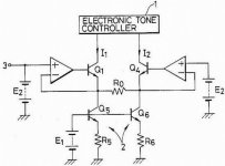
I have been playing around with this basic idea. In theory (at least in my head) the dif amps connected this way would have good current balance without using current mirrors on their collector loads nor the resistors that are not equal. The thing works in SPICE simulation, but I also constructed it in real life and seem to have a lot of problems. The currents are not equal even if I remove the VA stage transistors.....
My question mostly is, if anyone has tried such layout or what thoughts does it provoke in your head. For some reason the idea is attractive to me but as I don't have that much of experience, might be I'm totally overlooking some possible problems..
Ergo
Doesn't look like the differential amplifiers can work as such,
since they can't share a common current source. What you
appear to have is an independent current source for each
transistor, so no 'balancing' action can occur. In fact, it looks
sort of like a current mirror, but on the wrong side.
Self and Sloan in their books give some examples of rather
more complex differential amplifiers, some using complementary
feedback pairs, but I found them difficult to understand.
I don't really understand negative feedback either...I just take
it on faith that it works.
You've rediscovered the phono stage used in the Hafler DH101 preamp, were the feedback network is the RIAA and the output transistors are darlingtons. The current sources were just resistors to the rails.
Ergo
Have you seen my message to you in the 'Everything Else' section of the forum regarding my attempts to reply to your email?
Geoff
Have you seen my message to you in the 'Everything Else' section of the forum regarding my attempts to reply to your email?
Geoff
complementary schematic
Hi Ergo,
Please have a look at the GAS Thaedra or Thoebe schematic in the link. They used the same idea for there line amp and Ampzilla and Son of Ampzilla poweramp. It is more than 26 years old!
The scheme is also used to some extent by Elantic and Harris(now Intersil) in some of there IC's
http://home.earthlink.net/~narf1/thopho.jpg
I am a happy owner of a Ampzilla and I can tell you the circuit works best if <B>all four</B> inputtransistors are matched. You need a lot of them to find four equal!🙂
Elso:
Thanks for posting that schematic. I'm curious; is there a reason that the current sink/source resistors for the input diff pairs are returned to the emitter of the output device instead of the rails? It appears to be some sort of feedback. Otherwise, it looks very much like the Lin configuration that Borbely likes to use.
mlloyd1
crircuit detail attributed to James Bongiorno
Hi mloyd1,
I have no idea it seems to be a James Bongiorno speciality. He does it all the time in all his circuits.
BTW the HaflerDH200 also uses this scheme but without the detail you described. No wonder as JB worked for Hafler and SAE . SAE also uses the scheme in a lot of there amplfiers.
Hi mloyd1,
I have no idea it seems to be a James Bongiorno speciality. He does it all the time in all his circuits.
BTW the HaflerDH200 also uses this scheme but without the detail you described. No wonder as JB worked for Hafler and SAE . SAE also uses the scheme in a lot of there amplfiers.
gas ampzilla son of
Elso i have thaedra preamp and son of ampzilla i just love them
i know you love your ampzilla
Elso i have thaedra preamp and son of ampzilla i just love them
i know you love your ampzilla
posted by mlloyd1
I'm curious; is there a reason that the current sink/source resistors for the input diff pairs are returned to the emitter of the output device instead of the rails?
I believe that increases the compliance of the current source. Curcio does the vacuum tube equivalent with his Dyna mods.
I'm curious; is there a reason that the current sink/source resistors for the input diff pairs are returned to the emitter of the output device instead of the rails?
I believe that increases the compliance of the current source. Curcio does the vacuum tube equivalent with his Dyna mods.
- Status
- Not open for further replies.
- Home
- Amplifiers
- Solid State
- a bit different amp front end layout