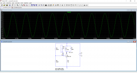
The schematic attached shows a single BJT oscillator using a biasing scheme which I found very interesting, and efficient. The 10kHz output sinewave is very clean considering the simplicity of the circuit. The oscillator uses an LC parallel resonator as the transistor's output. It taps some of its energy into a short coil to feed the base.
Inspection of the various currents under LTSpice shows that the LC resonator receives an energy pulse for a very short time during each cycle.
Inspection of the various currents under LTSpice shows that the LC resonator receives an energy pulse for a very short time during each cycle.
Attachments
Some general remarks: R4 can be incorporated in the Thevenin resistance of R2//R3 (Any fool can make things bigger, more complex, and more violent. It takes a touch of a genius, and a lot of courage, to move in the opposite direction ?)
Real inductors have parallel and series damping resistances, and cannot achieve a coupling K=1
Real inductors have parallel and series damping resistances, and cannot achieve a coupling K=1
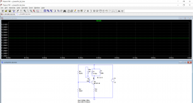
I tried your suggestion, but the oscillator failed to start. I used (R2 || R3) + R4 as the equivalent series Thevenin resistance and the voltage at R4's end when it is diconnected from the base. The new worked out values of R2 and R3 resulted in much higher resistances of 53.5k and 641.5k. The Thevenin voltage was calculated to be 1.09V.
Raising the supply voltage from 12V to 13V was enough for the circuit to work. However, why an extra 1V is needed if we are talking about EQUIVALENT circuit networks?
Raising the supply voltage from 12V to 13V was enough for the circuit to work. However, why an extra 1V is needed if we are talking about EQUIVALENT circuit networks?
Last edited: