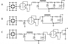
I've got an amp project going on another thread here. In that project I want to use a TV horizontal sweep damper tube as a "slow start" device for the B+. Currently I have option "A" in that schematic. But I was thinking... if the purpose of the damper is only to give me a slow B+... Why the heck am I putting it right behind my silicon diodes? It can be anywhere right? So I drew up options B and C in the picture. I'm liking C the best but want to run it past. Moving the damper down the chain allows me to use a much larger first filter capacitor (option B). But then I thought why not get a lot more filtering capacitance by moving the damper to the end of the whole train? (option C). All options have the same number of capacitors, just in different places (MRC is motor run capacitor as I wanted to end the filter train with a film capacitor).
Which do you like the best? Am I way off on something here?
Which do you like the best? Am I way off on something here?
Attachments
My preference. Lots of ways to skin a cat, but I think carries the best of all worlds. I would lose little caps across the diodes, too. All they do is let more noise through. Choose a soft recovery diode and let the dampers to their thing.
Essentially this is choke-input arrangement? I am using UF diodes though, the slugging caps came from tests done in the Merlin Blencowe book .
Actually, Blencowe argues that one cap across the secondary is what you want. You can use an RC if you want to get fancy about it.
I write to great lengths about it here: Taming the LM3886: Rectification and Snubbers – Neurochrome
My context is chipamps, but it could just as well be a tube amp. The underlying physics don't change.
As for your original question: The position of the damper shouldn't matter in steady-state. You may see some differences on startup and shutdown, though. I'd simulate that before committing one way or another. You may find that one of the configurations is better for long-term reliability of the damper.
Tom
Last edited:
Actually, Blencowe argues that one cap across the secondary is what you want. You can use an RC if you want to get fancy about it.
Tom
Thanks, yes he does say only one slugging cap is enough, I should change that too. Thanks. I'll read up on your link later.
I tend to prefer option A. This prevents excessive surge voltage on the power supply capacitors before the circuit downstream is warmed up.
My preference. Lots of ways to skin a cat, but I think carries the best of all worlds. I would lose little caps across the diodes, too. All they do is let more noise through. Choose a soft recovery diode and let the dampers to their thing.
That was my experience on the first valve mixer i designed.
If the diodes are noisy then you are using the wrong type of diodes.
Some say that valve rectification (soft) contributes to the valve sound.
Personally I haven't found that and now always use SS rectification.
Saves a lot of expense and room.
I tend to prefer option A. This prevents excessive surge voltage on the power supply capacitors before the circuit downstream is warmed up.
I see, my first nooby thought was that I could get more capacitance up in front of the damper, but yes that is a bigger surge. Also maybe it is indeed better to have most of the reserve capacitance after the damper also an argument for option A as long as the first cap after the damper is small. I'll try A on the bread board first when I get the parts together.
That was my experience on the first valve mixer i designed.
If the diodes are noisy then you are using the wrong type of diodes.
Some say that valve rectification (soft) contributes to the valve sound.
Personally I haven't found that and now always use SS rectification.
Saves a lot of expense and room.
In my case I'm not even thinking of that damper as a rectifier, I'm thinking of it as a cheap and simple B+ delay device. I don't like solid state timer with relay solutions. Delay tubes are expensive and no longer made anymore. I know the compromises on voltage loss, heat and space with a soft rectifier. I agree with you that valve sound vs silicon sound no difference as long as there is no sag happening.
Last edited:
- Home
- Amplifiers
- Tubes / Valves
- A, B or C and why?