Hey,
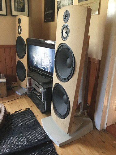
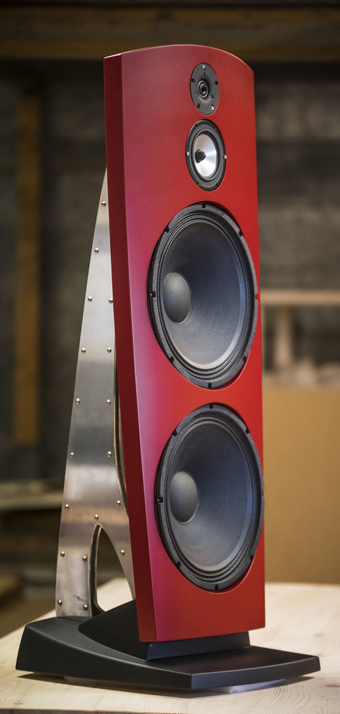
long time no see. Haven´t finished them yet, just wondering that are they too big or is my living room too small... 😉
Boards were about 1250 x 550 mm when gluing, but they could be bigger. Easier to bend and clamp if they are maybe 100mm wider. No chance of clamp marks.
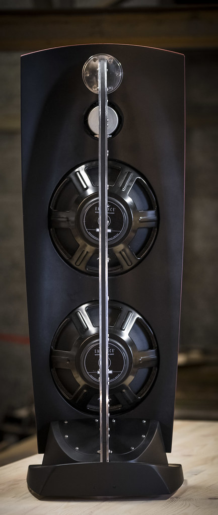
Final size of the baffles is 1210 x 490mm.
Those were quite hard to bend but they stayed nicely after gluing.
long time no see. Haven´t finished them yet, just wondering that are they too big or is my living room too small... 😉
Boards were about 1250 x 550 mm when gluing, but they could be bigger. Easier to bend and clamp if they are maybe 100mm wider. No chance of clamp marks.
Final size of the baffles is 1210 x 490mm.
Those were quite hard to bend but they stayed nicely after gluing.
Last edited:
Hey,
long time no see. Haven´t finished them yet, just wondering that are they too big or is my living room too small... 😉
Boards were about 1250 x 550 mm when gluing, but they could be bigger. Easier to bend and clamp if they are maybe 100mm wider. No chance of clamp marks.
Final size of the baffles is 1210 x 490mm.
Those were quite hard to bend but they stayed nicely after gluing.
Hi Eero
They are magnificent. I'm truly inspired. Well done.
Did you glue and clamp all the boards at one time, or if not, how many boards did you glue each time?
If I cut a 1200mm sheet in half, that'd be slightly less than 600mm width.
Thanks
Doug
Thank You! I´m glad that I can help!
MDF´s are 1220 x 2440 here, so there´s plenty for four boards. If they are 1200 x 2400 there where you are, you just get a few centimeters shorter baffle.
It´s better to glue all at once.
Spread the glue as fast as you can (with PVAc-glue. If you use slower glue like slow-hardening epoxy, there´s no hurry) in every other surface, and put plenty because there must no be any voids between boards!
Then lay all the boards on the mold, check that it their centerline is exactly lined with the molds centerline, and put two long screws through boards to the mold so that the boards stay firmly in place. Remember that the screwhole is in place that is going to be cut away later, I screwed through lower woofer and mid-tone. You can see the screwplaces taped in the mold.
It´s also nice to have table that is just right-sized. 🙂
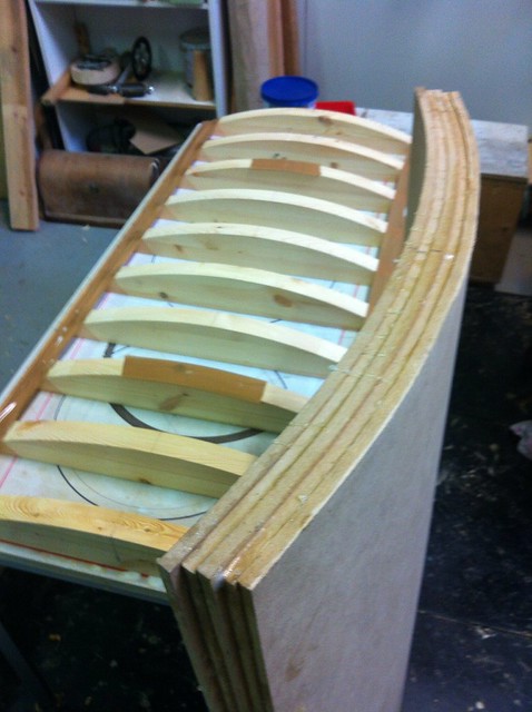
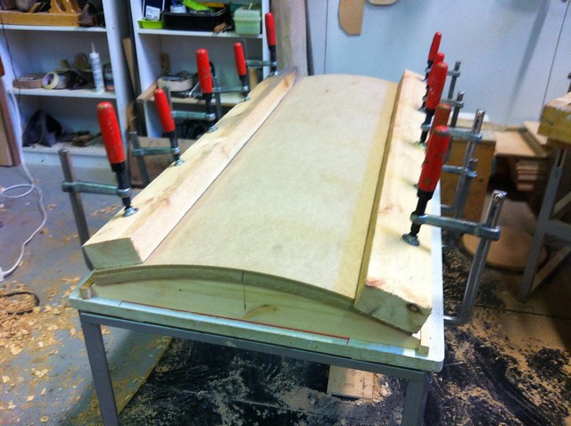
Then just put long, straight plank on either side and clamp it evenly both sides. I put all the clamps in place first quite loosely and then tightened them little at a time one by one as long as they went.
As you might notice, there´s no glue in this picture. It was taken while pre-bending them overnight to make them more "willing"... It is also good practice for gluing.
MDF´s are 1220 x 2440 here, so there´s plenty for four boards. If they are 1200 x 2400 there where you are, you just get a few centimeters shorter baffle.
It´s better to glue all at once.
Spread the glue as fast as you can (with PVAc-glue. If you use slower glue like slow-hardening epoxy, there´s no hurry) in every other surface, and put plenty because there must no be any voids between boards!
Then lay all the boards on the mold, check that it their centerline is exactly lined with the molds centerline, and put two long screws through boards to the mold so that the boards stay firmly in place. Remember that the screwhole is in place that is going to be cut away later, I screwed through lower woofer and mid-tone. You can see the screwplaces taped in the mold.
It´s also nice to have table that is just right-sized. 🙂
Then just put long, straight plank on either side and clamp it evenly both sides. I put all the clamps in place first quite loosely and then tightened them little at a time one by one as long as they went.
As you might notice, there´s no glue in this picture. It was taken while pre-bending them overnight to make them more "willing"... It is also good practice for gluing.
David; I have tried different kinds of coil and capacitors and they sound pretty nice to me now. But I won´t even try to tell any of you that they are correct in any way.
As I mentioned earlier, I do not know absolutely anything about audio-hifi, I was hoping that I could get some help here in that department.
I am more woodworking guy, so that is really my contribution to this forum.
As I mentioned earlier, I do not know absolutely anything about audio-hifi, I was hoping that I could get some help here in that department.
I am more woodworking guy, so that is really my contribution to this forum.
Thank You! I´m glad that I can help!
MDF´s are 1220 x 2440 here, so there´s plenty for four boards. If they are 1200 x 2400 there where you are, you just get a few centimeters shorter baffle.
It´s better to glue all at once.
Spread the glue as fast as you can (with PVAc-glue. If you use slower glue like slow-hardening epoxy, there´s no hurry) in every other surface, and put plenty because there must no be any voids between boards!
Then lay all the boards on the mold, check that it their centerline is exactly lined with the molds centerline, and put two long screws through boards to the mold so that the boards stay firmly in place. Remember that the screwhole is in place that is going to be cut away later, I screwed through lower woofer and mid-tone. You can see the screwplaces taped in the mold.
It´s also nice to have table that is just right-sized. 🙂
Then just put long, straight plank on either side and clamp it evenly both sides. I put all the clamps in place first quite loosely and then tightened them little at a time one by one as long as they went.
As you might notice, there´s no glue in this picture. It was taken while pre-bending them overnight to make them more "willing"... It is also good practice for gluing.
Thanks Eero.
Once again, your post is very informative.
1. Yes. I think I will try to find a steel-framed table on which to carry out the work.
2. With the climate in Australia, I doubt that PVA would allow enough working time.
3. The laminating (/veneering) I have done is with polyurethane glue. It has a long work-time. It is a foaming type glue, which has the benefit of being void-filling. Yes, you do need to use gloves and ensure ventilation, but that isn't difficult. It is also a little slippery, which helps in aligning the boards.
4. I like the idea of a pre-bend conditioning treatment for the boards. Did you try using kitchen plastic sheets between the boards? That will make them much easier to align for this task. When the time comes to glue, it is great - to stop the glue bonding the work to the frame and clamps.
5. I think it would also assist if the screw holes were pre-drilled. That way you could use a piece of thick wire at either end and thread all the boards on to them. Then remove the wire and put in a screw to retain them! (Then begin the bending.)
cheers
Doug
Last edited:
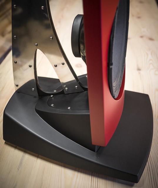
...its been more than a few years since I last looked cloely at a pair of these but
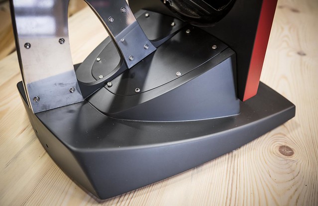
if I recall correctly there is a sectioned rubbery infill between the two rear metal supports. This acts both as a resonance damping agent and as carrier with cut channels for drive unit wiring.
Thank you for posting this very informative and interesting build.
if I recall correctly there is a sectioned rubbery infill between the two rear metal supports. This acts both as a resonance damping agent and as carrier with cut channels for drive unit wiring.
Thank you for posting this very informative and interesting build.
R909 clone Down Under
Hi Eero
Just a quick note to say that last night I began cutting timber to make a bending jig, along the lines of your design.
This is going to be a long project, but I'm aiming for a quality finish, as you've set such a high standard.
I'll continue cutting tonight, and I'll post some pictures as progress is made.
Given that I'm constructing a jig that will be reusable, is there anyone else near to Brisbane who is interested in constructing an OB "In the Spirit* of the R909"?
(* Eminence 15A's, Fostex FE168Es, tweeter <tba>.)
cheers
Doug
PS I started with the idea of a gloss painted finish, but now I'm considering a burl veneer all over.
Curious about the placement of the speaker? Given that sound is reflected from the back, it would see in any given room there would be a optimal distance from the wall behind.
Jamo R 909 -
Jamo : Search : 909 : Home
Steve/bluewizard
Jamo R 909 -
Jamo : Search : 909 : Home
Steve/bluewizard
Curious about the placement of the speaker? Given that sound is reflected from the back, it would see in any given room there would be a optimal distance from the wall behind.
Jamo R 909 -
Jamo : Search : 909 : Home
Steve/bluewizard
Hi Steve
Whether a speaker is OB or "boxed", there is a zone of optimum placement. The only thing that varies, IMHO, is the size and location of the "sweet zone".
Doug
Any quasi-anechoic measurements of them on and off axis ?
They look very good.
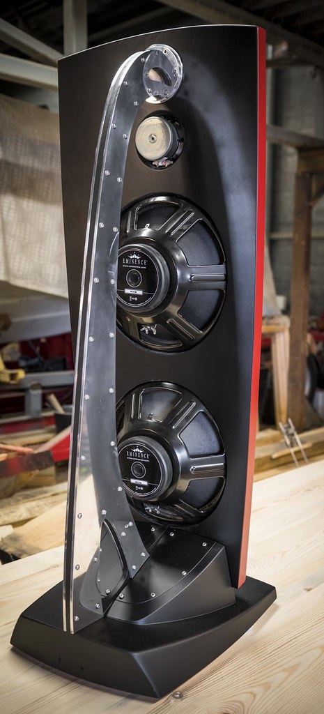
One thing maybe - you should have chamfer the opening for L15 from the back.
They look very good.
One thing maybe - you should have chamfer the opening for L15 from the back.
Last edited:
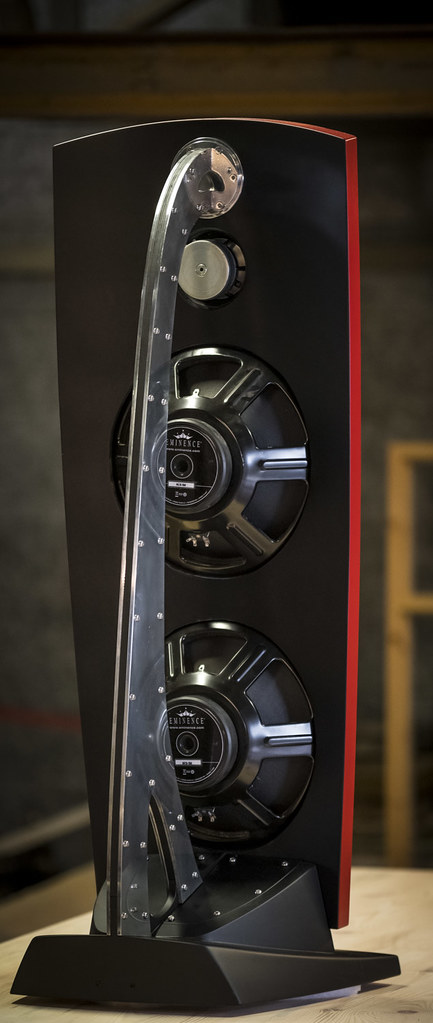
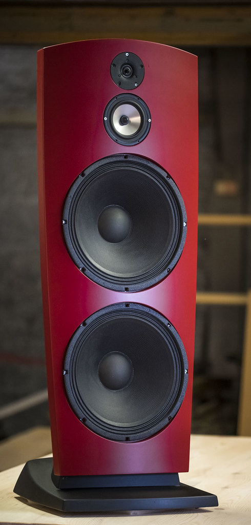
Beautiful!
Nicely detailed. I'm curious as to how you created a flat inset for the speakers with the front surface being curved...
Nicely detailed. I'm curious as to how you created a flat inset for the speakers with the front surface being curved...
Tim took the words right out my mouth. I've done a few curved lamination builds myself - using vacuum bagging and 5mm rubber-ply, but have always stuck with flat baffle sections for drivers. It'd be fun if you still had some photos of the jigging for routing those driver rebates.
Thank you very much, I am happy with them now.
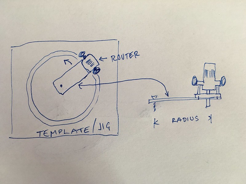
Flats are routed with top bearing flush router bit, with the template like this:
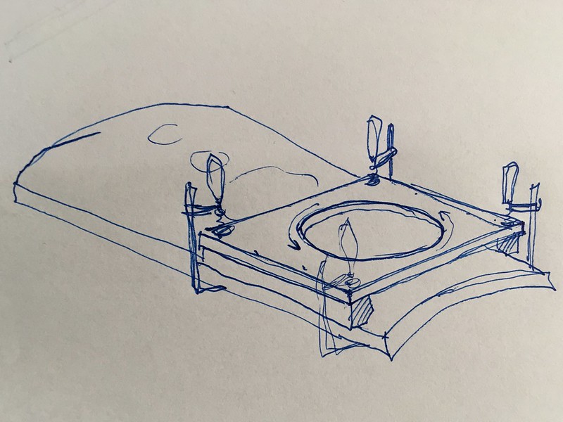
Hole in the template is first routed using router as a compass; piece of plywood is screwed to the bottom of the router and then plywood is attached to the centerpoint of the upcoming template with a screw, and then swing the router around it.
Zvu, no measurements coming, they sound good enough for me... 🙂
Flats are routed with top bearing flush router bit, with the template like this:
Hole in the template is first routed using router as a compass; piece of plywood is screwed to the bottom of the router and then plywood is attached to the centerpoint of the upcoming template with a screw, and then swing the router around it.
Zvu, no measurements coming, they sound good enough for me... 🙂
Last edited:
Congratulations, Eero!
Here is Stereophile's off-axis measurement, without normalization
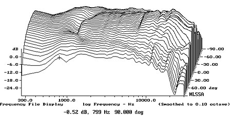
We can see that dipole radiation stops around 800Hz and there is a remarkable discontinuity around 1100Hz. Still, measured room response is quite nice. Because of the baffle width, there is not much to do with eq.
Here is Stereophile's off-axis measurement, without normalization
We can see that dipole radiation stops around 800Hz and there is a remarkable discontinuity around 1100Hz. Still, measured room response is quite nice. Because of the baffle width, there is not much to do with eq.
Last edited:
- Home
- Loudspeakers
- Multi-Way
- 909 clone