Now the d.c protect trigger at +2v d.c and -3v d.c.Replace 470k with 47k...
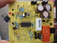
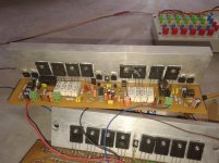
Here is the board after modification.
Now we have another problem.....when a little warm Tip31 and a d.c present simultaneously,the relay pulse continuously
Attachments


Last edited:
you have changed the time constant from 10seconds to 1second.
The DC detect should work with either time constant.
If it didn't work with that 470k, then there is something wrong. Is it leakage again? post3280.
Could the problem be that the electro is not charging up sufficiently, because the charging current is being wasted in leaking past the unreformed electrolytic.
Now the d.c protect trigger at +2v d.c and -3v d.c.
Here is the board after modification.
Now we have another problem.....when a little warm Tip31 and a d.c present simultaneously,the relay pulse continuously
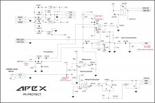
It's ok, 1N4148 add to the circuit.
Attachments
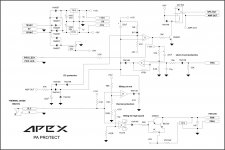
Yes of course. I will post soon.thimios can you post voltage measurements on schematic?
Here are.thimios can you post voltage measurements on schematic?
I can't understand why you want a second 4148 in series with negative trigger diode,this will add 0.6v
Attachments
Last edited:
Here are.
I can't understand why you want a second 4148 in series with negative trigger diode,this will add 0.6v
Second 1N4148 stop condacting from inverting input of OP amp D (about +1V) to AMP OUT... measurements are OK, what is transformer specifications, you must have 24V on fan and relay.
Last edited:
I haven't connect a fan this time only a 1k resistor because i have a small transformer(2x20v a.c 2x0.9VA) just for test.btw +/-15v are ok but i have -21v on the relay (when relay contact) instead of -24vSecond 1N4148 stop condacting from inverting input of OP amp D (about +1V) to AMP OUT... measurements are OK, what is transformer specifications, you must have 24V on fan and relay.
Last edited:
I haven't connect a fan this time only a 1k resistor because i have a small transformer(2x20v a.c 2x0.9VA) just for test.btw +/-15v are ok but i have -21v on the relay (when relay contact) instead of -24v
You must use 10VA transformer minimum.
Now the d.c protect trigger at +2v d.c and -3v d.c.
Here is the board after modification.
Now we have another problem.....when a little warm Tip31 and a d.c present simultaneously,the relay pulse continuously
this was the reason i remove this protection after few tests.there is some issue first dc detect circuit trigger from +15 vdc and problem with negative dc voltage too.second relay not quickly off as it should be. i did few test with dc all my speaker coil (only speaker coil ) blow in second then i did some experiment to solve.other issue is if protection relay off due to dc detect luckily save speaker now operator don't know that amp shut down due to dc comes or overheat he surely try to reset the amp after few min. this protection circuit relay should not on this time but relay of this circuit on and then off.yes relay on for half second but half second is enough to blow speaker like fuse. other hand apex stereo protection is very good dc detect relay is very fast.where about concern about this thread h900 amplifier that is best from best.thanks.
hi apexH900 can have 1200W maximum on 4R load.
Regards
Is it possible 2r times more power was also h900?
Unbalance input for B600
Hello Sir Mile... Please give advice on how to make this B600 input side unbalance.. I have already made the board but I'm not sure if it's correct or will work fine... I need your assistance so I can properly test my amp. I want it for unbalance input because I wanna use a buffer.
Thanks & Regards
Hello Mr. Mile.. I'd like to ask if its ok to cut-off the volume control based on the original schematic? I remove it because I wanna use input buffer. Hoping you can give an advice because I wanna build this amp in HB TEF version.
Many thanks
Hello Sir Mile... Please give advice on how to make this B600 input side unbalance.. I have already made the board but I'm not sure if it's correct or will work fine... I need your assistance so I can properly test my amp. I want it for unbalance input because I wanna use a buffer.
Thanks & Regards
Attachments

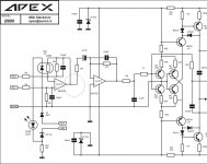
^if you already have this made...then just use either one of the inverting or non-inverting and you have an unbalanced input already....signal to any + or minus inputs and then signal returned to ground....
^if you already have this made...then just use either one of the inverting or non-inverting and you have an unbalanced input already....signal to any + or minus inputs and then signal returned to ground....
Yes I already made this according to the schematic without volume control Sir.
Thank you very much Sir Tony...
Regards

hi sir rohin my apex h900 amp
very nice clean work. .mje 340 ,350 also need heatsink.
- Home
- Amplifiers
- Solid State
- 900W H-class PA Amp with Limiter