Thanks Mile.Diode polarity is wrong on pcb and fan polarity is wrong on schematic,
Regards
I want to modify this in order to lower the d.c protection at about 1v d.c on loudspeaker out and the pro inp suitable to a hi-fi 100w amplifier or so.
Thanks Mile.
I want to modify this in order to lower the d.c protection at about 1v d.c on loudspeaker out and the pro inp suitable to a hi-fi 100w amplifier or so.
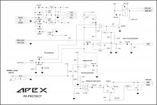
PRO input can be trigered from overload detect circuit with AC signal (B500, H900) or DC positive (AX16, HV23...) and it's power off/on reset.
DC protect can be trigered with +/-1V DC on amp out and it's auto reset.
Regards
I see that it is necessary to apply +15v or -7v in speaker terminal for protect activation. Is this normal?PRO input can be trigered from overload detect circuit with AC signal (B500, H900) or DC positive (AX16, HV23...) and it's power off/on reset.
DC protect can be trigered with +/-1V DC on amp out and it's auto reset.
Regards
I see that it is necessary to apply +15v or -7v in speaker terminal for protect activation. Is this normal?
Remove 22uF for test dc protection
Ok, do you mean that this circuit can be used to protect any amplifier without modifications?
I see also that led protect indicator lights a little after relay comes off.
I see also that led protect indicator lights a little after relay comes off.
Last edited:
Why do we need to remove the 22uF capacitor to allow the circuit to react to a DC input?
We don't need to remove the 22uF if we change test dc voltage very slow.
Ok, do you mean that this circuit can be used to protect any amplifier without modifications?
I see also that led protect indicator lights a little after relay comes off.
Yes this PA protecct can be use with any amp without modifications.
I don't think so,i have test this with a variable power supply with an 20 turn potentiometer and it is necessary to attach +15v d.c in order to come in protection mode.We don't need to remove the 22uF if we change test dc voltage very slow.
I don't think so,i have test this with a variable power supply with an 20 turn potentiometer and it is necessary to attach +15v d.c in order to come in protection mode.
I suggest this modification on circuit.
Attachments
So i will live with the first circuit🙂
Suppose this was used from you for years🙂
What will did you say for a bipolar capacitor 22uf?
Attachments
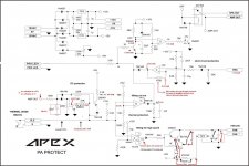
Thimios, adjust the 22uF downwards.
Try 20Hz input and check that the circuit does not trigger with maximum 20Hz output.
You may want to try it at anywhere from 10Hz to 20Hz for no trigger.
Keep making the capacitor smaller until it does trigger, then go back up one value.
You may find that 220k and 1uF is a filter value that allows the circuit to pass a full power 20Hz. That allows an MKT capacitor. For 10Hz you may find that 470k & 1uF works.
Hi AndrewT, you mean that this will be tested to an amplifier at max volume when input signal is from a function generator?Thimios, adjust the 22uF downwards.
Try 20Hz input and check that the circuit does not trigger with maximum 20Hz output.
You may want to try it at anywhere from 10Hz to 20Hz for no trigger.
Keep making the capacitor smaller until it does trigger, then go back up one value.
You may find that 220k and 1uF is a filter value that allows the circuit to pass a full power 20Hz. That allows an MKT capacitor. For 10Hz you may find that 470k & 1uF works.
What signal?
Sinusoidal or square wave?
Last edited:
20Hz sine wave adjusted (not max) to be just a tiny fraction below clipping at the output, should NOT trigger the DC detection.
But you have the choice of whether to apply a lower frequency for your no trigger passing signal.
But you have the choice of whether to apply a lower frequency for your no trigger passing signal.
This was tested this afternoon.Thimios, adjust the 22uF downwards.
Try 20Hz input and check that the circuit does not trigger with maximum 20Hz output.
You may want to try it at anywhere from 10Hz to 20Hz for no trigger.
Keep making the capacitor smaller until it does trigger, then go back up one value.
You may find that 220k and 1uF is a filter value that allows the circuit to pass a full power 20Hz. That allows an MKT capacitor. For 10Hz you may find that 470k & 1uF works.
The protection board was connected to an amplifier output .
Amplifier's power supply is +/-50v.
Generator was adjusted at a level that amplifier gives 28vrms on a 7R dummy. Frequency adjusted for 20Hz sinusoidal.
I ended up with a value of 2u2 .This is what i see for a correct value.
Pushing amplifier harder (hard clip) protection activated.
I must mention that with 22uf the protection never was activated even with very hard clipping.
Opinions please.
Last edited:
Now try 18Hz, and/or 16Hz, and/or 14Hz.
Does it trigger?
Does it trigger at a lower output voltage?
Are these lower frequency triggers acceptable to you?
BTW, you don't need the 7r0 dummy load. The detector is only detecting DC and very long duration
portions of the output voltage. It is not detecting current. That is done in a different part of the protection system.
Last edited:
Did you reform the 22uF electrolytic?I must mention that with 22uf the protection never was activated even with very hard clipping.
What is the unreformed leakage current?
Will that leakage current change the detection levels?
I repeatedly recommend that electrolytics be reformed before assembly.
I just reformed a 47uF 16V recycled electro (from a very old television). The leakage voltage measured across a 100k charging resistor @ 16V was down to 4.0mV. That is 40nA of leakage and equates to 0.000053CV
It will be used across a Zener+Diode voltage reference for a cascoded jFET LTP running at 6.9Vdc. Most Builders just throw in any cap and don't bother checking what they have done.
Last edited:
- Home
- Amplifiers
- Solid State
- 900W H-class PA Amp with Limiter