Hello, I would like some help determining what to investigate or troubleshoot to determine why the harmonic distortion driving an 8ohm load is out of spec for my restored Sansui AU-517 and why 8ohm THD may be worse than 4ohm when supply voltage isn't limiting. The amplifier noise is within spec and THD driving a 4ohm load is within spec. However, at output voltages greater than 15dbv, distortion into 8ohms exceeds distortion into 4ohms. The distortion at 8ohm is also heavily odd order, while distortion driving 4 ohms is more evenly mixed odd and even. Supporting measurements plotted below and schematic attached. Amplifier bias is stable, and the issue exists across both channels. There is a fair bit of power supply noise, but it is within spec. Input is direct to the power amp with the preamp separated. Measurements are made on a QA402.
The amplifier was recapped with several diodes and signal level transistors replaced. I did not measure the amplifier prior to restoration, but it worked well with the typical lazy and noisy "I need a recap" sound.
My goal with hobby vintage audio restoration is to return to manufacturer spec without replacing output transistors or modifying the circuit. I've measured 4 vintage audio restorations, and this is the first to be far out of spec.
Thanks,
Joe
THD+N vs output voltage (Note that this measurement is prior to proper warm up, hence the reduced THD in the second plot vs watts after warm up)

THD+N vs output power

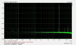
1khz, 8ohms, 20W, showing excessive odd order distortion

The amplifier was recapped with several diodes and signal level transistors replaced. I did not measure the amplifier prior to restoration, but it worked well with the typical lazy and noisy "I need a recap" sound.
My goal with hobby vintage audio restoration is to return to manufacturer spec without replacing output transistors or modifying the circuit. I've measured 4 vintage audio restorations, and this is the first to be far out of spec.
Thanks,
Joe
THD+N vs output voltage (Note that this measurement is prior to proper warm up, hence the reduced THD in the second plot vs watts after warm up)
THD+N vs output power
1khz, 8ohms, 20W, showing excessive odd order distortion
Attachments
Last edited:
Schematic as a picture below if that helps, but it loses resolution from PDF. Any ideas why THD would increase with higher Ohm loads? I tried a couple more different load values and the increasing THD is consistent to least 10 Ohms. Voltage isn't limiting. I thought a high output impedance might do it, but output impedance is low. During the restoration I did make a couple changes to the circuit values, increasing capacitance of C02, C04, C11, and C14 as an attempt to decrease noise.

Hi Joe,
It depends on exactly what you did, and what parts you used (if they are real as well).
I was going to post the measurements on my AU-517 that was rebuilt, but I lost the drive and files as a result. I have another to do. I ended up with extremely low distortion.
It depends on exactly what you did, and what parts you used (if they are real as well).
I was going to post the measurements on my AU-517 that was rebuilt, but I lost the drive and files as a result. I have another to do. I ended up with extremely low distortion.


Thanks for pulling these up. At one watt into 8 Ohms our results are almost identical. I measure THD+N of 0.02% and THD of 0.002%. It is around 9 or 10W where my measurements start to get funny as seen in the figures. Audiovintage.fr has restored and measured an impressive number of 517s and their measurements at 1W are consistent with ours, but they measure at 65W and find that THD is flat with power (within rated power), which is where my measurements vary out of spec.Found a couple for you ...
So many parts are replaced in these restorations, I was hoping that the specific THD behavior across power and load would provide clues for troubleshooting.
Hi Joe,
At higher powers, the connections to your loads can really increase distortion measurements. The relay can also mess things up, can you test before the relay? You also need a Kelvin connection to your loads, I use the industry standard Dale 250 watt, 1%, non-inductive heat sink mounted resistors.
The next one I work on, I'll check the high power distortion again.
I'm using an RTX 6001 analyser.
Well here I measured the Sansui AU-517 one channel at a time but still driving both channels. Although the 8ohm vs 4ohm issue is the same, measured distortion went down considerably and the inflection point in the 8-ohm distortion also increased from 7W to 10W. I think this all suggest that the odd 8 ohms distortion is measurement error, and I have some things to learn to get good <-70db distortion measurements from this budget analyzer.


I just measure over the load resistor as shown below. I'm familiar with kelvin connections for measuring resistance and voltage, but it didn't occur to me that there would be an impact on harmonic distortion.At higher powers, the connections to your loads can really increase distortion measurements.
Hmm, non-standard load resistors for one. My measurements come off right at the resistors. The proper dummy loads have a large bolt on each side (axial) and the measured connections are on top of the power in connections. I have no idea what your load resistors are like under load.
They look like the things they sell as “audio dummy loads”. Those are just big resistors put in a fancy heat sink so they look cool and more money can be charged.
All metal to metal interfaces have SOME distortion. Some even partially rectify - which is to say, HIGH distortion. Metal to oxide gets worse. The lower the distortion floor has to be, the cleaner everything in your setup has to be. And quite literally, cleaner. Not only layout but metallurgically. And no, cheap Chinese gold plating is not always the correct answer. I’ve seen the underlying metal corrode right through it. I imagine the distortion produced by the connector to be quite high……
Once 2nd and 3rd order distortion in the amplifier gets lower than a Speakon connector with typical materials, I quit trying to reduce it. Still worth trying to reduce high order distortions, as their IMD contribution is what tends to sound unnatural.
I use Speakon connectors to adapt various output connectors to the dummy load panel. Everything past that is crimped ring terminals. The Speakon connectors require periodic cleaning and replacement. Good thing the jack comes out for the front or it would be a real pain to replace!
The cheap Speakon connectors don't perform well. Cost of doing business, having to replace cable connectors on the bench.
The cheap Speakon connectors don't perform well. Cost of doing business, having to replace cable connectors on the bench.
- Home
- Amplifiers
- Solid State
- 8ohm THD exceeds 4ohm THD and out of spec, restored Sansui AU-517