What sort of output transformer do you plan to use? 800 plate volts might be a bit high if you want to stay within rated plate dissipation ratings. You should be able to get away with 600 volts triode connected. I would put some sacrificial limiting resistor on the screen in case the plate cap disconnects. Attaching some curves I have from somewhere.

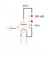
Thank you for your information. But I want to know, if follow my picture attached. G2 is not direct connect to Anode but Zener diode between them. Is it still call triode connection ?
At full power, and loaded with an output transformer, the anode voltage will swing roughly between 2 x B+ and almost 0 V. But the string of zeners can't 'follow' the anode voltage at a distance of 400 V anymore when the anode voltage get's below 400 V since the screen grid voltage can't go below 0 V.
So I don't think your idea will work. When swinging below 400 V the tube will not work as a triode. The distortion will be terrible.
So I don't think your idea will work. When swinging below 400 V the tube will not work as a triode. The distortion will be terrible.
Yes, you are right.At full power, and loaded with an output transformer, the anode voltage will swing roughly between 2 x B+ and almost 0 V. But the string of zeners can't 'follow' the anode voltage at a distance of 400 V anymore when the anode voltage get's below 400 V since the screen grid voltage can't go below 0 V.
So I don't think your idea will work. When swinging below 400 V the tube will not work as a triode. The distortion will be terrible.
Thank you very advise
Any advise, please
Maybe look around at others that have built 814 SE amplifiers. A few exist.
Fairly straightforward once you have chosen an operating point and have an appropriate output transformer.
I had an 814 amplifier for a while. One of my 814s died most likely because I had carried it around since I was a kid.
I went with 845 just because it allowed for somewhat more plate current for the same amount of filament power.
The 814 Beam Power tube is not normally used as an audio tube, but it can be used as an audio tube.
But do the below exercise, in order to get an idea of what happens when the screen voltage is held to a constant voltage . . . (Versus when a Beam Power tube, including the 814 is in Triode Wired mode).
Look at the data sheets for Beam Power audio tubes.
Find the graphs of plate IV curves that also have screen g2 IV curves on the same graph, versus the grid voltage.
The screen is held to a constant voltage on those graphs.
When the grid g1 is at or near 0 Volts versus the cathode voltage, two things happen:
The plate current goes up, and the plate current goes up.
The screen current goes up very drastically, because the screen voltage is still high and is not allowed to drop down, even though the grid g1 volts is at or near 0 Volts.
That same thing could happen to an 814 if the screen voltage is held constant (Beam Power mode), lots of screen current, and grid g1 at or near 0 Volts.
But when an audio Beam Power tube is in Triode Wired mode, guess what happens . . . the screen voltage goes down just as far as the plate voltage does. With the screen at a low voltage, the screen current is not very large, even with the grid g1 at 0 Volts.
The only issue I see with operating the 814 in Triode wired mode, and with the plate and screen both at 600V, is if the screen arcs and shorts to any tube wiring and elements such as either the grid g1, or arcs and shorts to the Beam Formers.
Remember, the grid G2 maximum dissipation is 10 Watts. 10 Watts / 600V = 16.7mA.
Also, do not forget, when the B+ to the plate and screen are both 600V, when the tube is near cutoff, the plate and screen voltage will both be near to 1,200V. That too might cause the grid g2 to arc to either the grid g1, or the Beam Formers.
So I recommend using as high a B+ that will not cause such arcing, and not cause more than 10W screen dissipation.
Suppose that is 500V or 600V for example . . . do not use a zener from the plate to the screen g2.
I would describe the operation with a zener from the plate to the screen g2, as not being true Triode Wired Mode.
And, it would certainly limit the output power, and possibly have a nasty sound as the screen current abruptly drops to below the zener's required minimum current to be at the rated zener voltage, and then comes on again abruptly.
Just my opinions.
And now, a question for you:
Do you intend to use the 814 in Class A2 drawing grid g1 current?
Last edited:
Post # 2 graph of plate curves shows both the 814 in Triode Wired mode (plate and screen g2), and the 845 plate both going all the way to 1400 Volts.
It seems that the screen g2 of the 814 that was used on the curve tracer did not arc over at 1400 Volts.
It seems that the screen g2 of the 814 that was used on the curve tracer did not arc over at 1400 Volts.
Sure I will try class A2 , but I don't know how to modify the circuit.Post # 2 graph of plate curves shows both the 814 in Triode Wired mode (plate and screen g2), and the 845 plate both going all the way to 1400 Volts.
It seems that the screen g2 of the 814 that was used on the curve tracer did not arc over at 1400 Volts.
Would you please give me advise at you early convenience.
Current schematic as below.
Attachments
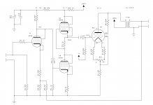
Some remarks:
- The bias of the 814 is indicated as -24 V. With B+ being 800 V, this value should be something like -85 V.
- There is no decoupling (= capacitors to ground, like C3+C13) between R19 and R21 while there should be.
- The maximum heater to cathode voltage of the 6CH6 is 90 V so you need a seperate elevated heater supply for the upper 6CH6's.
Sure I will try class A2 , but I don't know how to modify the circuit.
Would you please give me advise at you early convenience.
Current schematic as below.
A2 operation require AC-power to drive the g1 of the output tube (unlike A1 operation, which only require voltage, no g1-current).
Therefore some sort of low impedance and dc-coupled driver stage is required, such as triode driven transformer, cathode follower or NFET source follower.
Current schematic can not very easily be modified for A2.
Study this: https://www.tubecad.com/2018/01/blog0410.htm
- Home
- Amplifiers
- Tubes / Valves
- 814 DHT triode connection