OK I've plagued a few of you over this a few times in the past, but now I'm ready to build.
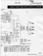
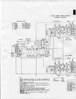
Here's the givens: The opts are ex a jukebox running 7868 power tubes. Specs on the jukebox schematic indicate the opts are 6.6k primary and around 25W. There is no u/l tap, and the secondaries are multi-tapped. We can assume they are not audiophile quality.
The ptx is from the same donor. It has a bunch of interesting windings - two heater windings, a 5 volt and a centre tapped HT that appears to be around 360-0-360.
Rectification to be decided. Filtering to be decided. Regulation to be decided.
The power tubes will be 1625s - 807s in different trousers. Pentode mode. The STC spec sheet gives a set of specs for AB1 that need 360V at the anode, 270V G2, -22.5V bias, 45 pp drive for 26.5W output. Cool! Matches my iron reasonably.
Now the help. I want minimum tube count - I just like the simplicity. So I'm looking to dissimilars like the ECF802 to provide gain and splitter - the pentode section for gain, the triode for cathodyne splitter.
The ECF802 is capable enough - the Ik ratings for both sections are ok - 15ma for the pentode, 10ma for the triode, so drive shouldn't a too much of a problem should it?
Limitation is Vkf at 100 volts, but with only 45Vpp drive required I should be able to stay under that.
What the hell - I've got a handful of them and I don't intend to spend on anything other than passives in this project. If you have suggestions, bear that in mind.
Feedback will be required obviously to deal with the combination of pentodes and under-educated opts. I'd like to keep it short and simple so a schaded approach seems the answer. But can it be used in the gain/splitter configuration I'm proposing? And if so, what do I need to figure in the math, cos to tell the truth, both Schade and Broskie have me a bit fuddled in the detail.
Or do I just get basic with some global NFB to the ECF802 pentode?
Comments invited.
Attachments
Go for a real triode/pentode: 6F12P with both sections Gm close to 20mA/V and triode mu of 100! The pentode has 70 mu when triode-strapped. They should be run at 10-20mA. Cheap on Ebay. The pentode is great for driving Schaded circuits.
You mentioned that there are multiple taps on the OPT, which simplifies tweaking of NFB (without changing the circuit).
I'd leave VAS cathode unbypassed for starters and apply feedback from the secondary (to VAS cathode resistor) only if needed. I wouldn't mess with plate to grid feedback unless absolutely necessary - you first need to figure out whether you're getting enough volume anyway.
Other than that it sounds pretty straightforward. Pentode section of ECF802 appears to be pretty linear at high current but gets rather ugly past Vg1 = -2V and/or at low current so you'll have to bias it close to the Pd curve and pick the operating point as close to Vg1 = 0V as you can afford to (IR LED bias to remain close to 1.2Vish ?). Keep Vg2 at or above 150V to maintain more headroom (you could go for red LED in case of Vg2 = 200V).
Good luck with your build and remember to keep us updated 🙂
You could use a simple ecc81 or a ccs loaded ecc88. Just like I did. both schedules are here:
http://www.diyaudio.com/forums/tube...s-input-stage-phase-splitter.html#post1993966
Gain of both is about 30x. so with a 0.5 vrms input you should reach your 45 vpp.
Both have reasonably low Ri, so that should be good.
Or is only a dissimilar an option?
/joke mode on/ If you build the CCS version, you can experience the burn-in effect yourself, dont worry, in a few days the sound gets a lot better... /joke mode off/
You could use a simple ecc81 or a ccs loaded ecc88.
Sorry, saw too late that you already have the ECF's...😱
Good luck...
hey! Yeah - all my stuff takes significant burn in. It takes a loooooooong time to accept that the sound it makes is as good as it will ever be :-(
Hehehehehehehehehehehe
Forgot to put that in the info above - I aim at a 2V pp input so I need a voltage gain of around 50 (or a bit more) at the pentode before some feedback...
Hehehehehehehehehehehe
Forgot to put that in the info above - I aim at a 2V pp input so I need a voltage gain of around 50 (or a bit more) at the pentode before some feedback...
hey! Yeah - all my stuff takes significant burn in. It takes a loooooooong time to accept that the sound it makes is as good as it will ever be :-(
Hehehehehehehehehehehe
Forgot to put that in the info above - I aim at a 2V pp input so I need a voltage gain of around 50 (or a bit more) at the pentode before some feedback...
Mu of the pentode section, triode strapped is about 40.... is that too low?
Has some nice characteristics in triode....
http://www.tubes.mynetcologne.de/roehren/daten/ecf802pentode_as_triode.pdf
I already did an 807PP project, though my design was a good deal different. I did, however, make some discoveries that are apropos.
807s like to make high order harmonics. Though the spec sheet calls for THD= 1.8%, a lot of that is h5 and higher. Running open loop, it sounds quite nasty on some program material (Ozzy became all but unlistenable) though Andre Rieu wasn't so bad. 807s definitely need the assistance of local NFB. In my design, this was parallel feedback taken to the grids of the cathode follower grid drivers to "skip over" the 807's reverse transfer capacitance to avoid making a high pass filter with the feedback resistors. As per O. Schade's recommendation, the local NFB was trimmed so that 10% of the plate Vp was fed back. (~ 7.0db(v) of local NFB)
Since the 807 is an RF type, if you don't feed it RF it'll make its own. That means plate stoppers, and screen stoppers. For that, I made coils (N= 10; #18AWG; ID= 7/16th inch; space wound in parallel with 100R / 2W C-comp resistors, mounted right at the plate cap.
For screen stoppers: 1K5 / 0.5W C-comp resistors were needed to remove the last of the snivets that showed at plate current cutoff.
Once that was done, an additional 6.0db(v) of gNFB was needed to clean up the rest of the pentode nasties, and improve woofer damping. Get the open loop design right, and you don't need gargantuan amounts of gNFB. Too much, and you start to get that solid statey sound. Yuck!
yep and thanks Miles - I'd kinda taken it as read that the anode and screen stoppers that both you and shoog (and other 807/1625 exponents) recommend would be de rigeur.
I have Vixen schematics liberally strewn around my hard drive, so I will study it again and get back if I have specific questions.
Thanks for you ever present and patient guidance!
I have Vixen schematics liberally strewn around my hard drive, so I will study it again and get back if I have specific questions.
Thanks for you ever present and patient guidance!
Have you considered strapping the 807's as triode? You get about 12 watt's out of a 7k OPT. On the spectrum analyzer shots, i dont see any higher order harmonics. (they appear at clipping though...) The mu is 4, and you don't need nfb.
Power is King! Triodes are for wussies! If I had trannies big enough I'd be building the 80 watt version...
You'll be recommending parafed SE next if I'm not careful.
You'll be recommending parafed SE next if I'm not careful.
You'll be recommending parafed SE next if I'm not careful.
I wouldn't dare...😀
- Status
- Not open for further replies.
- Home
- Amplifiers
- Tubes / Valves
- 807 pp build project - whose in?