One last test is did you check voltage on the 807 control grids with no negaitve feedback? See if the grid voltage clips at the same time as the output?
I think you are starved for plate voltage. If you have a way to generate a bias supply, you could see what fixed bias gets you. You would be gaining 30V for the plate. Using three 9V batteries in series would also work as a quick test. Tie the 470K resistors for 807 grid bias about 30V negative and replace the 220 ohm cathode resistor with 10 ohms.
Also check page 5 of the attached 5881 datasheet. It is an example of ultralinear use with roughly the same values.
View attachment 5881.pdf
Your input and driver tubes might be clipping early. Yes, that will reduce the power before clipping.
But here is another thing to check:
The maximum Screen voltage for an 807 is 300V in Pentode mode.
The maximum Screen voltage for an 807 is 400V in Triode mode.
I estimate that the maximum Screen voltage for an 807 is about 350V in Ultra Linear mode.
You are operating in Ultra Linear mode, with 420V on the screen.
The only thing that is saving the 807 Screen from destruction is the 4.7k Screen resistor.
4.7k on the Screen limits the output power from the amp.
But . . . you can not reduce the 4.7k to a lower resistance . . . that would endanger the Screens (especially for sine wave testing of maximum power, or playing the amp at music volume that is at clipping).
Another test would be to remove feedback (disconnect at 50 ohm node) and remove 807's, then measure voltage gain from input to 807 grid leaks (preferably a probe across each 470k, or a meter across each 470k to maintain balanced loading). The voltage on the 470k grid leaks should be same magnitude. Measure the voltage swing at clipping (Vpk) and check if clipping is close to symmetric for each grid leak signal. If you do a frequency sweep, you should see the input stage cathode circuit, and the anode circuit, droop the gain at low, and high, frequency points. Best to use a variac if the 807's aren't in to avoid generating too high a B+ for your filter caps and couplings caps.
PS. you are using filter caps that are uF and not mF ?
PS. you are using filter caps that are uF and not mF ?
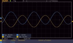
I connect G2 through 470R resistor for each to 300V power supply, and output is little bit higher.
In PS I have 2x47uF in series, choke 0,4H, 500uF, from which I take B+ for OPT etc.
In PS I have 2x47uF in series, choke 0,4H, 500uF, from which I take B+ for OPT etc.
Last edited:
Since the sims show that 16W output is expected for UL there may not be anything wrong with your input or driver stages. Could it just be that the designer advertises peak power (aka music power) rather than rms power.
Does each grid waveform clip symmetrically at both top and bottom ?
Do you want to try and sketch a loadline for 6SN7 triode and estimate what the Vpp should get to at on-set of clipping, given the B+ voltage and cathode voltage for the splitter stage.
Do you want to try and sketch a loadline for 6SN7 triode and estimate what the Vpp should get to at on-set of clipping, given the B+ voltage and cathode voltage for the splitter stage.
Last edited:
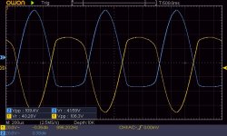
No, clipping is not symmetrical.
I can try do this drawing, but as bohrok2610 wrote, I am afraid that it is waste of time to do anything else. But if you can help, I can do that, I will learn something new 🙂
I have one idea yet, use driver from
http://www.jogis-roehrenbude.de/Verstaerker/GU50-Grommes/Schaltung.gif
and check if I am able to get more power. If not, then result is clear. 807 is no interest tube for me anymore 😛
Attachments
Last edited:
I would expect the 807 g1 grids to conduct whenever the grid becomes positive with respect to the cathode (at that point they will clip).
(Each 807 g1 grid will only clip in One Direction).
Is that what I am seeing in the graphs in Post # 30?
If so, that looks normal to me.
When you change from Ultra Linear to Pentode mode (Actually Beam Power mode), the grids will clip at exactly the same drive voltage (same grid g1 to cathode voltage).
The output transformer primary is 6600 Ohms. Suppose the DCR is 330 Ohms (no manufacturer DCR rating).
The secondary is 8 Ohms. Suppose the DCR is 0.4 Ohms (no manufacturer DCR rating).
The insertion loss would be 1 dB.
1 dB is a power ratio of 1.259:1
16 Watts at the output of a transformer that has a 1 dB insertion loss . . .
1.259 x 16 Watts = 20.144 Watts.
The 807 plates are producing 20 Watts, but the output transformer "eats up" 4 Watts.
Are we getting any closer to understanding your amplifier?
Last edited:
Nothing is 'clear' from the results you have shown imho, and it would be a waste of time to think that any testing that you haven't done so far is a waste of time.
Based on only one marked up schematic in post #1, I will use that for assessment. A bogey 6SN7 with a per triode loadline of 47k, and Vak max of 295V - 113V = 182V, and 0V crossing of 182/47k = 3.9mA, has a Vgk=0V limit of Vak=40V. So triode max Vpp swing is 182V - 40V = 142Vpp. The centre idle is circa Vak=110V, or 110+113 = 223V relative to 0V - which is a bit higher than the 196V shown on your circuit diagram, which is likely due to hot biasing to alleviate cutoff region distortion. The indication on the schematic that Vgk=123-113 = 10V at idle (2.1mA cathode current) is suspect.
Your results in post #27 indicate less than 60Vpp swing. The clipping results in post #30 indicate about 110Vpp. Biasing for better symmetry may get you well beyond 60Vpp before onset of clipping.
That doesn't stop the output stage from having issues, but at least you allow the first 2 stages to perform without getting in to clipping, and so ease the job of the feedback.
#30 shown clipping on G1 on both 807, but 807 are removed, and FB disconnected.I would expect the 807 g1 grids to conduct whenever the grid becomes positive with respect to the cathode.
(Each 807 g1 grid will only clip in One Direction).
Is that what I am seeing in the graphs in Post # 30?
If so, that looks normal to me.
When you change from Ultra Linear to Pentode mode (Actually Beam Power mode), the grids will clip at exactly the same drive voltage (same grid g1 to cathode voltage).
I do not remember reading what the primary impedance of your output transformer is.
What is that specification?
OPT is 6k6 40W.
Nothing is 'clear' from the results you have shown imho, and it would be a waste of time to think that any testing that you haven't done so far is a waste of time.
Based on only one marked up schematic in post #1, I will use that for assessment. A bogey 6SN7 with a per triode loadline of 47k, and Vak max of 295V - 113V = 182V, and 0V crossing of 182/47k = 3.9mA, has a Vgk=0V limit of Vak=40V. So triode max Vpp swing is 182V - 40V = 142Vpp. The centre idle is circa Vak=110V, or 110+113 = 223V relative to 0V - which is a bit higher than the 196V shown on your circuit diagram, which is likely due to hot biasing to alleviate cutoff region distortion. The indication on the schematic that Vgk=123-113 = 10V at idle (2.1mA cathode current) is suspect.
Your results in post #27 indicate less than 60Vpp swing. The clipping results in post #30 indicate about 110Vpp. Biasing for better symmetry may get you well beyond 60Vpp before onset of clipping.
That doesn't stop the output stage from having issues, but at least you allow the first 2 stages to perform without getting in to clipping, and so ease the job of the feedback.
One more time, I check all DC voltages on 2 firsts levels. Everything matched, only B+ for 6SN7 is 320V.
I try to draw on paper your number, and will see. Thanks
zdenoeddie,
I edited my Post # 30, (after you first read it).
More information:
The output transformer primary is 6600 Ohms. Suppose the DCR is 330 Ohms (no manufacturer DCR rating).
The secondary is 8 Ohms. Suppose the DCR is 0.4 Ohms (no manufacturer DCR rating).
The insertion loss would be 1 dB.
1 dB is a power ratio of 1.259:1
16 Watts at the output of a transformer that has a 1 dB insertion loss . . .
1.259 x 16 Watts = 20.144 Watts.
The 807 plates are producing 20 Watts, but the output transformer "eats up" 4 Watts.
And what about the DCRs of the output primary and secondary?
If it calcuates to 1 dB of loss, congratulations, your 807s are producing 20 Watts.
Are we getting any closer to understanding your amplifier?
If the g1 signals on the 'missing' 807s (807s removed) is clipping then that is the drivers or input tube clipping.
The clipping appears to be at about 20V. If the 807 g1 to cathode is -20V, then you will not get more output with the input stage and drivers (unless the alternation is in the other direction [the larger alternation] drives the 807 grids more positive.
Oh, the 18 or 20V was your Post # 27. But that is just before the 807s draw grid current.
Last edited:
113V on 27k = 4.2mAOne more time, I check all DC voltages on 2 firsts levels. Everything matched, only B+ for 6SN7 is 320V.
(320V-196V)/47k = 2.6mA per triode, or 5.2mA into common cathode resistor.
So something is NQR.
The 47k resistor between PS and B+ for 6SN7 in the schematic cannot be correct since the voltage drop would be about 200 volts.
zdenoeddie,
I edited my Post # 30, (after you first read it).
More information:
The output transformer primary is 6600 Ohms. Suppose the DCR is 330 Ohms (no manufacturer DCR rating).
The secondary is 8 Ohms. Suppose the DCR is 0.4 Ohms (no manufacturer DCR rating).
The insertion loss would be 1 dB.
1 dB is a power ratio of 1.259:1
16 Watts at the output of a transformer that has a 1 dB insertion loss . . .
1.259 x 16 Watts = 20.144 Watts.
The 807 plates are producing 20 Watts, but the output transformer "eats up" 4 Watts.
And what about the DCRs of the output primary and secondary?
If it calcuates to 1 dB of loss, congratulations, your 807s are producing 20 Watts.
Are we getting any closer to understanding your amplifier?
If the g1 signals on the 'missing' 807s (807s removed) is clipping then that is the drivers or input tube clipping.
The clipping appears to be at about 20V. If the 807 g1 to cathode is -20V, then you will not get more output with the input stage and drivers (unless the alternation is in the other direction [the larger alternation] drives the 807 grids more positive.
Oh, the 18 or 20V was your Post # 27. But that is just before the 807s draw grid current.
Infors regarding OPT
https://www.hammfg.com/files/parts/pdf/1650HA.pdf
A 40 W spec of the OPT doesn't mean your circuit is capable of 40 W output. See my earlier post.
- Home
- Amplifiers
- Tubes / Valves
- 807 PP amp René CARIOU