When you say that you can't get 16W out of the amp, do you mean you clip before reaching that output?
Is the B+ not sagging too much when you reach this output?
Just ideas.
Is the B+ not sagging too much when you reach this output?
Just ideas.
Yes, 16W before clipping. B+ is stable as hell. But I found another schematic with a little different values etc. so I try to modify it. It is struggle second day, and I dont understand where is issue.
You need to know where does it clip first, which is the limiting factor.
At the 6SL7 level, at the splitter or at the power stage.
Could be also too much feedback.
At the 6SL7 level, at the splitter or at the power stage.
Could be also too much feedback.
I disconnect FB, and search for limitation. The degradation is already present on input 😕 I think that is possible only with FB connected.
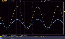
Yellow output 8R, blue input on G of first tube. Is it possible, that this is issue connected with current grid?
Yellow output 8R, blue input on G of first tube. Is it possible, that this is issue connected with current grid?
Attachments
I put FB a little bit low and little but high (1k and 15k instead of 3k formerly), and output limits still at the same level....  I am helpless.
I am helpless.
I built a very similar PP amplifier with Russian G807 tubes, although with custom 25:1 transfomer working on 8 ohms load. B+ was also 425V. I could get only 10 ... 12W @k=1% in open loop. I am afraid this tube and supply voltage could offer only this much. (BTW 10W tube audio power is more than enough for me). Fixed bias would give some more power before clipping.
If you want to raise the output power, use the 807 as a pentode: connect g2 to stabilized +300V, and go up with the anode voltage up to 600V. But then you will need a different OPT, different phase splitter, different bias setting (fixed bias as mentioned), ...
If you want to raise the output power, use the 807 as a pentode: connect g2 to stabilized +300V, and go up with the anode voltage up to 600V. But then you will need a different OPT, different phase splitter, different bias setting (fixed bias as mentioned), ...
I have seen an amplifier with 807s but using a transformer with a 4.1K load. Used it for a car amp for a few years without any problem with about 410 volts and no resistors on the screens. Was a Dynaco A470 Ultralinear transformer.
420V is probably too low to reach full power. How much voltage do you have across the 220 ohm bias resistor?
You may be able to get closer by going with fixed bias to get higher plate voltage.
420V is probably too low to reach full power. How much voltage do you have across the 220 ohm bias resistor?
You may be able to get closer by going with fixed bias to get higher plate voltage.
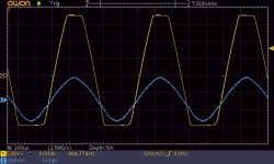
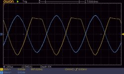
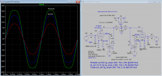
"Feedback disconnected. Measured input with anode on 6SL7, and grid on both 807" :
Hard to decipher this. Three pictures, six traces, but it seems clipping is not caused
by the first tube.
Sure all indicated dc voltages are in range ?
Hard to decipher this. Three pictures, six traces, but it seems clipping is not caused
by the first tube.
Sure all indicated dc voltages are in range ?
I built a very similar PP amplifier with Russian G807 tubes, although with custom 25:1 transfomer working on 8 ohms load. B+ was also 425V. I could get only 10 ... 12W @k=1% in open loop. I am afraid this tube and supply voltage could offer only this much. (BTW 10W tube audio power is more than enough for me). Fixed bias would give some more power before clipping.
If you want to raise the output power, use the 807 as a pentode: connect g2 to stabilized +300V, and go up with the anode voltage up to 600V. But then you will need a different OPT, different phase splitter, different bias setting (fixed bias as mentioned), ...
I also try this today morning, pentode connection, Ug2=300V, it looks the same as UL. Probably I will use it at all, I think it is more safe for this tube than this UL.
I want to spend old main transformators for this, but it give me only up to 340V, so I have to switch for another one, which give me 430V, and has also winding for -Ug1, so it will be next step to use fixed bias, if this will work correctly.
For me is 10W also good, but not for 40W OPT and 430V B+ 🙂 It will be the same with EL84 with cheaper OPT and lower B+.
420V is probably too low to reach full power. How much voltage do you have across the 220 ohm bias resistor?
You may be able to get closer by going with fixed bias to get higher plate voltage.
It can be possible, but then developer of this schematic is not right with his description.
Voltage on 220R resistor is around 32-33V at B+ = 430V.
"Feedback disconnected. Measured input with anode on 6SL7, and grid on both 807" :
Hard to decipher this. Three pictures, six traces, but it seems clipping is not caused
by the first tube.
Sure all indicated dc voltages are in range ?
Yes all DC voltages are ok (I have to use 22k instead of 47k to drop voltage for 6SN7 etc., but according another schematic there have to be 300V).
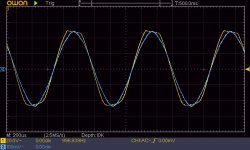
On every picture is input signal together with every one as described.
It seems now, that problem is really not in 6SL7 input stage... but in 6SN7 phase splitter. I have already try to trim this part, but without success.
Next, it is easy to reduce Rk27k (the one with 113 V indicated) to check max.
excursion of the splitter stage.
Pictures in post 8 seem to indicate that this is overdriven due to lack of supply.
excursion of the splitter stage.
Pictures in post 8 seem to indicate that this is overdriven due to lack of supply.
Having 22K instead of 47K on the plate resistors for the 6sn7 will not help. Need to have the correct values there.
Also the transformer you use has 6.6K primary rather than 6K so you would need slightly more plate voltage. Also I doubt the amplifier as drawn in the schematic would really reach 30W.
Also the transformer you use has 6.6K primary rather than 6K so you would need slightly more plate voltage. Also I doubt the amplifier as drawn in the schematic would really reach 30W.
Next, it is easy to reduce Rk27k (the one with 113 V indicated) to check max.
excursion of the splitter stage.
Pictures in post 8 seem to indicate that this is overdriven due to lack of supply.
I try 10k+25k pot instead of this 27k Rk for 6SN7, but with little value deformation appear in signal. B+ is 320V as always.
Having 22K instead of 47K on the plate resistors for the 6sn7 will not help. Need to have the correct values there.
Also the transformer you use has 6.6K primary rather than 6K so you would need slightly more plate voltage. Also I doubt the amplifier as drawn in the schematic would really reach 30W.
Yes you are right, I change plate resistors, and nothing help.
But I think that 6k6 and 6k is not so different values, to achieve only half of "nominal" power. Probably this is blind way for me, with 807 tubes. Probably switch to gu50. But I will try 6L50 before, but I am afraid that result will be similar.
Last edited:
Even 24W is quite low for 40W OPT 🙂
As I already written, I try pentode mode, Ug2=300V, Ua=430, and output was the same.
I am afraid that driver is not so good in this way. I am still dreaming about 6SJ7 and 6N7 driver.... does anybody know anything about that?
As I already written, I try pentode mode, Ug2=300V, Ua=430, and output was the same.
I am afraid that driver is not so good in this way. I am still dreaming about 6SJ7 and 6N7 driver.... does anybody know anything about that?
- Home
- Amplifiers
- Tubes / Valves
- 807 PP amp René CARIOU