Hey guys
So I manage to build my new Subwoofer amp with 800W RMS output power powered by a SMPS (this smps can handle 2 of this amp easily)
I'getting some kind of oscillation on my output signal at about full power
Here's the video:
YouTube
What do you think it's wrong here? does this came from my power supply and how could I make sure of that?
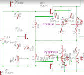
here's the schematics of my amp
My Amp.png - Google Drive
I'll appriciate any help
So I manage to build my new Subwoofer amp with 800W RMS output power powered by a SMPS (this smps can handle 2 of this amp easily)
I'getting some kind of oscillation on my output signal at about full power
Here's the video:
YouTube
What do you think it's wrong here? does this came from my power supply and how could I make sure of that?
here's the schematics of my amp
My Amp.png - Google Drive
I'll appriciate any help
Last edited:
I am not quite familiar with this kind of topology, but I would self suspect the combination of Miller compensation on VAS and the large value od R-gate on output mosfets. Maybe go from 470R to a smaller value. Best would be to check what frequencies the oscilations itself has.
Loosing stability on the maximums swing seems like a problem when the parasitic capacitances of the mosfet are going large due to small voltage drop over device.
It depends also on the layout, hopes that the leads to mosfet driver are not too long, luckily MJE340 is slow enough to not oscilate in most cases withour series resistor in base.
Last edited:
I see no resistor between the emitters of the driver pair. No bias current for MJEs?
Sajti
My bad
The schematic looks like this
My Amp2.png - Google Drive
I am not quite familiar with this kind of topology, but I would self suspect the combination of Miller compensation on VAS and the large value od R-gate on output mosfets. Maybe go from 470R to a smaller value. Best would be to check what frequencies the oscilations itself has.
Loosing stability on the maximums swing seems like a problem when the parasitic capacitances of the mosfet are going large due to small voltage drop over device.
It depends also on the layout, hopes that the leads to mosfet driver are not too long, luckily MJE340 is slow enough to not oscilate in most cases withour series resistor in base.
I will check the lower value for gate resistors
here's a shot from my project
IMG_20190406_125822.jpg - Google Drive
I will check the lower value for gate resistors
here's a shot from my project
IMG_20190406_125822.jpg - Google Drive
In this kind of layout you have to add a resistors ca 100ohm in series with the cables to output stage. They have high inductance, and this forms with the high input capacity of mosfets an oscilator. I myself would fear to make such connection to a bunch of mosfets on cooler.
You are quite lucky that nothing is burning here.
I made 2 of this amp but with +-80 volts supply and it's running for 2 years without any problems
the wire to the base of drivers are shilded
isn't 100 ohm a bit too much???
still no bias - it has to be between emitters Q12 and Q14.
how much bias current is adequate here?
Then if only difference is 10V supply lower this one to 80V and problem solved.I made 2 of this amp but with +-80 volts supply and it's running for 2 years without any problems

1. Agree there needs to be a resistor between the emitters of q12 and q14. It is hard to imagine the amplifier behaving sensibly without it.
2. Use of 22pf Miller cap is very very low indeed. Especially seeing mje340 /350 in the Vas and drivers. I would not be surprised to see this closer to 220 rather than 22!
3. Mje340 makes a very poor VAS driver. Look for something more of a video driver - they are too slow and in the VAS exhibit charge storage so in clipping you see a delay before recovery.
You need to start by fixing 1. And 2. To really expect things to work properly.
Also r17 and r18 are in an odd spot.....
Agree with you. I guess R17 and 18 should be between the emitters of the drivers for the MOSFETs. Also ten IRF MOSFETs have about 30nF input capacity, and this Q want's to be driven. Also this could cause spikes and distortion.
A cascade Vas would perform better then a single MJE340.
Also the current source with Q10 could bring you oscillation. Try it first with diodes. If it works stable, change it and try again.
Also as noted before, 22pF is way to small. Try up to 1nF to be save, and then reduce to min 100pf. Always look at 10khz square wave performance.
Last edited:
For a subwoofer amp, I think that going for a cascade VAS or a fast VAS transistor is useless, anyway you can really go up with the miller cap from 22p to like 220p for to be safe from global oscilation. But there can be a local oscilation - that can be said from the frequency of the oscilation itself. As for the bias, i think that these 470R here can do the job for 5-10mA which can be adequate i think.
Attachments
For a subwoofer amp, I think that going for a cascade VAS or a fast VAS transistor is useless, anyway you can really go up with the miller cap from 22p to like 220p for to be safe from global oscilation. But there can be a local oscilation - that can be said from the frequency of the oscilation itself. As for the bias, i think that these 470R here can do the job for 5-10mA which can be adequate i think.
I reaplaced 22pf miller cap with a 220pf and replace those two 470 ohms resistors with a single 220 ohms between two emitter of mosfet's drivers
It did reduce the oscillation but not completely and there's still some moving noise at top and bottom of the output signal that come and goes
Do you test with full supply voltage? And with all 10 + 10 MOSFETs? Because, as I said, so many have a lot of input capacity, and that's a problem.
R9 could also be a problem.
R20 makes actually not really sense. You could remove it ( not shorten it. The degeneration resistors R3 - R6 seems a bit high. 100ohms should be enough.
Another thing: did you ground the entire circuit? If the hole thing is floating, this could cause also oscillation.
R9 could also be a problem.
R20 makes actually not really sense. You could remove it ( not shorten it. The degeneration resistors R3 - R6 seems a bit high. 100ohms should be enough.
Another thing: did you ground the entire circuit? If the hole thing is floating, this could cause also oscillation.
Last edited:
I reaplaced 22pf miller cap with a 220pf and replace those two 470 ohms resistors with a single 220 ohms between two emitter of mosfet's drivers
It did reduce the oscillation but not completely and there's still some moving noise at top and bottom of the output signal that come and goes
can you check the frequency of the oscilations ? This can explain whether it is a global oscilation or a local one (myself I am quite sure its local in output stage)
In some triple stage configurations it was really necesarry to add a base stopper resistor for the driver, or in worst cases a small damping resistors (ca 10Ohm )in the collectors of the drivers and a small cap (100p) on the BC junction of drivers. - In case where local oscilations appear in the output stage.
Emitter resistors to output and base resistors Q12 and Q14.
Why circuits oscillate
http://www.audioworkshop.org/downloads/AMPLIFIERS_OSCILLATION_BJT_CIRCUITS.pdf
Why circuits oscillate
http://www.audioworkshop.org/downloads/AMPLIFIERS_OSCILLATION_BJT_CIRCUITS.pdf
- Status
- This old topic is closed. If you want to reopen this topic, contact a moderator using the "Report Post" button.
- Home
- Amplifiers
- Solid State
- 800W amp oscillation