Guys, hello, I'm from Russia, so I apologize for my English, I use a translator. I collect the 8-channel amplifier. The basis is an amplifier of the active mixer Dynacord PowerMate 1000. Drew Multisime scheme, it works, but a very large distortion at 20 kHz and a very large quiescent current. Help the errors will be very grateful to you, thank you.
Attachments
Probably, it is necessary to introduce an additional correction of the op-amp, I understand you correctly?
Hi Alexandr,
Well 🙂 Q25 was upside down, making the whole bottom half of the output stage sort of "dead". R16 bias trimmer was in a dangerous position - if the central pin would lose connection, quiescent current would grow uncontrolled. Overall gain was a bit too high (29db is some kind of a standard). Some of the base stoppers are were too high-value. Made a few corrections with regards to compensation. Looks much better now 😎
Cheers,
Valery
Attachments
Valery, a good day, yes, indeed, there are my mistakes =)! I even threw overcurrent protection, I do not need to be a different protection scheme. Put resistors emitters drivers Q3-Q25 to 22 Ohm, I read that they should be more resistors emitters of the output transistors 100 times, it's true is not it? Resistors bases of the output transistors larger resistors emitters of the output transistors in a 10 time, is that correct? You have the bases of the output transistors resistors more in 1000 than you explain it? Multimeter XMM 1 shows a large quiescent current of about 1.12 amps, this is too much for the amplifier should be in the region of 40-100 mA. At 20 KHz square pulse looks like a trapezoid. In short, it is necessary to dig =)!
Hi Alexandr,
Emitter load for the drivers is set based on the drivers' quiescent current you'd like to have. Assuming 4 pairs of BJTs you use, 25mA is reasonable. It's better not to connect those resistors to the output, but use one 47R resistor, shunted by 0.47uF-1uF capacitor, helping to re-charge the bases' capacitance faster.
You have to check the quiescent currents with no input signal - the easiest way is to set your input amplitude to 1 fVp (practically zero) - see the attached model, I saved it this way. You will see that the quiescent current of the output devices is around 85mA.
Also - if you use THD meter in your model - better always set its Fundamental freq. to the same value as the input frequency. Otherwise it slows down the simulation, showing the wrong values anyway.
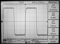
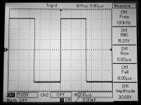
This design is rather slow - that's why your square wave response looks pretty much like trapezoid.
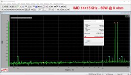
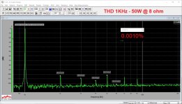
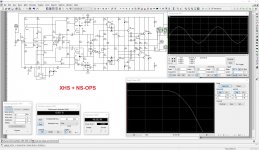
As an example of more mature design, I have attached one of my old XHS front-ends (2014) in combination with non-switching OPS - rather similar topology idea, but having some "specialties". All the measurements are made on the live prototype, built and tested. Having open loop bandwidth wide enough ensures small difference in distortion levels throughout the audio frequency range.
Let me know if you will have questions.
Cheers,
Valery
Attachments
-
Dynacord_PowerMate_1000_1600-vz2.zip628.2 KB · Views: 60
-
 DSC_0373.JPG489.9 KB · Views: 65
 -
 DSC_0372.JPG445.2 KB · Views: 62
 -
 52-XHS-IMD-14-15k-20v.JPG289.5 KB · Views: 143
 -
 51-XHS-THD-20k-20v.JPG277.3 KB · Views: 155
 -
 51-XHS-THD-01k-20v.JPG284.1 KB · Views: 162
 -
 00-XHS-Sim.JPG453.2 KB · Views: 161
 -
 DSC_0374.jpg518 KB · Views: 154
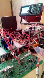
Dear Valery, adjusted power after replacing resistors emitters drivers and output transistors distortion decreased by an order. At 1 kHz everything is normal, the distortion in the normal 20 KHz too bad, 100 kHz turned Saw =)! To hang up the oscilloscope to the output of the 2nd stage, rushing out. Due to the slowness of the amplifier then there is no problem, so to speak, it is almost 100 percent. The problem is when the op amp stage.
P.S. I think you say in Russian, too, it would be possible to talk on the Russian site, and then translator translates not very good. I'm have in vkontakte and have vegalab, and have forum.cxem.net, for example =)!
P.S. I think you say in Russian, too, it would be possible to talk on the Russian site, and then translator translates not very good. I'm have in vkontakte and have vegalab, and have forum.cxem.net, for example =)!
Attachments
Guys, hey, it was the resistors of the differential stage, changed them for the experience of 6 кOhms (who were on 1kOhms), power began to move right up to 800 kHz. However, everything was a matter of trial and error. I'll be digging on the internet mode of operation of the differential stage.
- Status
- Not open for further replies.
- Home
- Amplifiers
- Solid State
- 8-channel amplifier