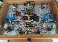
This amp feature auto bias, auto DC balance, very low bias current setting, 10 ma is good enough, non match power tubes will working fine. I try KT88 and 6550. Driver tubes works with 6dj8 or 12au7/12ax7. Output transformer was Hammond 1650N. B+ around 560 Volt at idle.Driver supply was regulated at 450 volt, bias voltage supply was regulated and adjustable.
Attachments


I was hoping you would explain that. I'm not sure I see how it works, if it does. Who designed it?
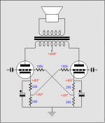
It's Blumlein “garter circuit”, cross feeds a sampling of each output tube’s current conduction via a tap in the cathode resistance to the other tube’s grid. Is kind of autobias, but with a few caveats. Now it's might well be "Broskie Cross-Refenced Auto Bias Circuit" ?.
Amplifier auto bias circuits: Alan Dower Blumlein's garter circuit
Blumlein’s Garter Circuit Revisited
Amplifier auto bias circuits: Alan Dower Blumlein's garter circuit
Blumlein’s Garter Circuit Revisited
Attachments
Where did I see this before 😕 Aha yes, Dynaco ST-70 Auto Bias version 😀
In this case it looks like the loop gain is too high, I think it will flip from max bias to min bias and back.
Mona
In this case it looks like the loop gain is too high, I think it will flip from max bias to min bias and back.
Mona
It's Blumlein “garter circuit”...
It's difficult to discuss the intent when the designer is not here to explain, but...
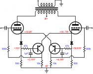
The OP claims auto bias and auto balance. It is not. It is sampling tube A current and adjusting tube B bias in response to that. This has a balancing effect, but not an auto-biasing effect. The only auto-bias comes from being partially cathode biased. Perhaps a Spice simulation can quickly show how well it works.
A circuit that provides both auto bias and auto balance would have an adjustable independent reference and circuits to sense each tube's current and adjust each tube's bias to match the reference.
The OP also seems to think the super-cold biasing of the tubes is somehow an accomplishment and/or related to this scheme. It's not at all clear to me what that is all about. "10 ma is good enough". Good enough for what?
Edit: A simple method of auto-bias and auto balance is to put a CCS under each tube. Here is the circuit Broskie suggests:
Attachments

Last edited:
Thank you for the explain, I will changed from auto balance to balancing effect.
The transistor was not act from max bias to min bias,it was working on linear area, I set output tube cathode at 200mv I measure transistor collector Voltage closed to the bias supply voltage, when the output increased that voltage starting drop to closed to zero and the output was at maximum about 24.5v at 8 ohm load.
The transistor was not act from max bias to min bias,it was working on linear area, I set output tube cathode at 200mv I measure transistor collector Voltage closed to the bias supply voltage, when the output increased that voltage starting drop to closed to zero and the output was at maximum about 24.5v at 8 ohm load.
Attachments

Pwgtang, what is the purpose of this thread? I'm not sure what you're trying to accomplish here.
Are you asking a question? If so, what is the question? The original post doesn't contain a question.
Are you asking a question? If so, what is the question? The original post doesn't contain a question.
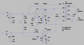
I've done like Broskie and put 2 tubes in parallel on one side to simulate a tube of the same type but with significantly different gm.
If you run this circuit, here is what happens:
If you bias it for 10mA per side, there is no balancing. The 20R resistors don't develop enough voltage to turn the transistors on to a significant degree. So you will find that the upper side essentially passes twice the current compared to the lower tube. 100% imbalance.
As you increase the bias, the balance circuit starts to work. But as you take it up to 67mA in the lower tube (37W) you have 99mA in the upper. So the balancing action is not particularly useful in the normal range of possible operation.
Last edited:
I build a Mullard 5 many years ago and now retired and I had time to try different circuits
for fun, I try the dynamic self cathode bias from Patrick Turner website. It work very good.
Then after a while I think I can get more watt output by used fix bias circuit, I found those output tube even I bought as match quad but not too match and run too hot. I try to build a amp with low idle current and not required tight mach tubes. Thank you for the link to Blumlein's Garter circuit. And the simulation.
1. Post # 7.
I like that circuit.
But use a resistor that is far less than 1Meg Ohm.
And keep in mind, the total current in the output is 100mA.
It is Class A Only, not Class AB.
As soon as one tube cuts off completely, there is no no additional current in the other tube; That is Class A.
Class AB is where one tube cuts off, and the other tube current keeps increasing.
2. Garter Bias
Yes, Garter Bias works real well when it is working.
But if one tube gets Gassy, or gets shorted, its current increases a lot . . .
And that causes the other tubes current to increase a lot too.
Therefore, I will not use Garter bias.
I never understood the attraction of the garter circuit. It attempts to balance the tubes in what is essentially a destabilizing fashion.
If tube A drifts away from the design intent operating point, it causes tube B to also go in the same direction. And so on. Assuming there isn't enough positive feedback to cause the whole thing to avalanche, the best you can hope for is a balanced circuit that operates at a quiescent point that is different than design intent.
If tube A drifts away from the design intent operating point, it causes tube B to also go in the same direction. And so on. Assuming there isn't enough positive feedback to cause the whole thing to avalanche, the best you can hope for is a balanced circuit that operates at a quiescent point that is different than design intent.
I have built a dozen amps with it that simply work and require no adjustments, even with off-balance bulk tubes. My daily use amps use it and have been absolutely trouble free for a couple years, twelve or more hours a day.
Lingwendil,
The next time you have a chance, Choose one of your Garter Bias amplifiers.
Take out the Garter Bias, and calculate Individual self bias resistors to give the same quiescent current that you had with the Garter Bias. Then bypass the Individual self bias resistors with enough capacitance to ground.
For a typical Garter bias circuit that I saw, the cathodes each had two 500 Ohm resistors in series to ground; and the Rg of the other stage returned to the junction of the 500 Ohm resistors.
Removing the bottom 500 Ohm resistor, returning the remaining 500 Ohm resistor to ground; and connecting the Rg to ground. Do for both push and pull.
Now, there will be a little more Plate to Cathode voltage, because there no longer is the voltage drop of the bottom 500 Ohm resistors. So the remaining 500 Ohm ressistors will need to be increased a little to keep the same quiescent P-K voltage, and P current (perhaps 600, 700 Ohms or more, but less than 1000 Ohms?).
Unless you have really badly matched output tubes, you may be pleasantly surprised how
well balanced the Push and Pull currents are.
I know that you do lots of things with Vacuum Tubes. This might be another experiment for you.
Let me know if you try it. I am not going to build a Garter Bias amp. But if I had one I would try it myself.
Thanks!
Last edited:
I am not going to build a Garter Bias amp. But if I had one I would try it myself.
It's simple enough to simulate in Spice, you don't need to build it.
dgta,
How do you simulate two 6L6 tubes that are badly matched?
Do you have the correct models, etc?
Simulations only work as good as the software, the models . . . and more.
The late great Bob Pease had a few things to say about simulation;
tube op-amps, optimizing an op-amp, etc.
I bet there are some here who remember his many words of wisdom.
He had a regular column, "Pease Porridge", in EDN magazine.
6A3,
Look at post #11 above. I copied the idea from Broskie. You simulate a gross imbalance by putting two tubes in parallel on one side. Simple and effective.
I do remember Pease Porridge. What's the name of the other guy with the column where he had a tricky circuit design quiz/question and he published the answer in the next issue?
- Home
- Amplifiers
- Tubes / Valves
- 75 watt ultra linear power amp