Finally the Innvotek 7" showed up and it works great!!! So crisp and clean,
I see that it lists a contrast ratio of 150:1... I wonder if this is a meaningless relative value when comparing to a ~450:1 monitor or if it really has significance?

I recieved a tracking number from them through the Canadian Post office. This is all it shows:
2005/02/22 16:53 Arrival in destination country
2005/02/22 03:29 Dispatched from origin country
2005/02/21 21:25 Dispatched from Canada
2005/02/21 19:51 MONTREAL, QC Received/processed at sortation facility
Were you able to track yours after it came to the US?
2005/02/22 16:53 Arrival in destination country
2005/02/22 03:29 Dispatched from origin country
2005/02/21 21:25 Dispatched from Canada
2005/02/21 19:51 MONTREAL, QC Received/processed at sortation facility
Were you able to track yours after it came to the US?
HiLLBiLLY said:150:1 is very low and will be noticeable when its projected
From the pictures I have seen and what people have posted - the Innovatek is a clone of the Lilliput with the exact same LCD screen.
Well they didn't copy it to well then as the Lilliput has a 200:1 contrast ratio buddy
http://cgi.ebay.com.au/ws/eBayISAPI.dll?ViewItem&category=14946&item=5752949496&rd=1
http://cgi.ebay.com.au/ws/eBayISAPI.dll?ViewItem&category=14946&item=5752949496&rd=1
The Hercules Prophetview 720 and Samsung 151MP have the exact same LCD panel yet the companies report different specs. I don't see how an LCD panel can have a different contrast ratio depending upon who installs it, so I assume it is a marketing ploy.
Innovatek 7” dismantle
Ok so now its time to do a preliminary take apart of the Innovatek 7” TFT-LCD Monitor. Keep this in mind, this is the first time taking this one apart and putting it back together, I took some measurements that I need to make a mount for it. I have yet to dismantle the panel; I’ll be doing that after I have a mount ready for the panel, UV glass, and fresnels. I’ll be making documentation on that part of the project as well.
Step one: Making sure it works.

As you can see I have an Xbox plugged in through video 3. It has a little glare but I had to set up a light in order to get good pics. Ok so now we know it works, take the time to unplug everything and get ready to dismantle the case.
Step two: Finding all the outside screws and opening the case.

Here is a pic of the back, it looks as if there are only 5 screws, however, in mine I found only 4. The blue circle shows a hold that would lead you to think there is a case screw in there, there wasn’t one in mine but there may be one in others. The yellow circles indicate the only 4 screws that I could find, they only seem to hold on the back plate and other then that, they have no purpose.

See, it’s all they hold. The case is only held together by snaps, just by applying a little bit of pressure and pulling them apart SLOWLY!!! It should pop right off, did for me.
Step three: Looking around inside, and cables.

BECARFUL!!! This is the inside of the case; there are some long and short cables in there. Disconnecting the cables isn’t hard, just don’t yank them they may rip apart.
Red: the tan latch is small, just pop it up by rotating it 90 degrees, make sure no to just pull out the 40 pin FFC wire. Firmly grip the blue backside and the wire together and pull out the wire slowly, it should just come right out.
Yellow: this is a smaller FFC cable, it is just held in by pressure, again just hold the wire and blue backing and pull out slowly, slides right out.
Blue: Now is just the LCD power cables for the light on the inside of the LCD panel. I’ll show how to take that apart at a later date.
Step four: Removing the control board.

this step is very simple, there are only four screws that hold the board down, two of which are hidden by a piece of electrical tape that protects the two protruding cables highlighted in red, and a heat shield in the opposite corner. When taking out the board from the back of the case remember there is an audio jack and the video 3 jack that protrude through the case, so lift it out at an angle. There is also a cable connecting the one lonely speaker to the control board highlighted in yellow, it just unplugs easily, and if you notice there is also a second speaker plug. I may feel like taking apart an old speaker set to include in the projector box
Step Five: Removing the LCD panel and buttons.

This is the simplest part, only four screws hold in the LCD panel itself to the case, along with a piece of metal as well. Just unscrew and remove the metal, and lightly pull up. The buttons on the panel are just two screws, yet again just unscrew and remove.
Step Six: Plugging everything back in and testing.

I think this step is self explanatory, just make sure no metal leads or wire ends are touching, or else you may short out the board and wasted $200.
Hope this is helpful, if you have any questions just ask
If anyone else has anything to add feel free to do so.
Ok so now its time to do a preliminary take apart of the Innovatek 7” TFT-LCD Monitor. Keep this in mind, this is the first time taking this one apart and putting it back together, I took some measurements that I need to make a mount for it. I have yet to dismantle the panel; I’ll be doing that after I have a mount ready for the panel, UV glass, and fresnels. I’ll be making documentation on that part of the project as well.
Step one: Making sure it works.
As you can see I have an Xbox plugged in through video 3. It has a little glare but I had to set up a light in order to get good pics. Ok so now we know it works, take the time to unplug everything and get ready to dismantle the case.
Step two: Finding all the outside screws and opening the case.
Here is a pic of the back, it looks as if there are only 5 screws, however, in mine I found only 4. The blue circle shows a hold that would lead you to think there is a case screw in there, there wasn’t one in mine but there may be one in others. The yellow circles indicate the only 4 screws that I could find, they only seem to hold on the back plate and other then that, they have no purpose.
See, it’s all they hold. The case is only held together by snaps, just by applying a little bit of pressure and pulling them apart SLOWLY!!! It should pop right off, did for me.
Step three: Looking around inside, and cables.
BECARFUL!!! This is the inside of the case; there are some long and short cables in there. Disconnecting the cables isn’t hard, just don’t yank them they may rip apart.
Red: the tan latch is small, just pop it up by rotating it 90 degrees, make sure no to just pull out the 40 pin FFC wire. Firmly grip the blue backside and the wire together and pull out the wire slowly, it should just come right out.
Yellow: this is a smaller FFC cable, it is just held in by pressure, again just hold the wire and blue backing and pull out slowly, slides right out.
Blue: Now is just the LCD power cables for the light on the inside of the LCD panel. I’ll show how to take that apart at a later date.
Step four: Removing the control board.
this step is very simple, there are only four screws that hold the board down, two of which are hidden by a piece of electrical tape that protects the two protruding cables highlighted in red, and a heat shield in the opposite corner. When taking out the board from the back of the case remember there is an audio jack and the video 3 jack that protrude through the case, so lift it out at an angle. There is also a cable connecting the one lonely speaker to the control board highlighted in yellow, it just unplugs easily, and if you notice there is also a second speaker plug. I may feel like taking apart an old speaker set to include in the projector box
Step Five: Removing the LCD panel and buttons.
This is the simplest part, only four screws hold in the LCD panel itself to the case, along with a piece of metal as well. Just unscrew and remove the metal, and lightly pull up. The buttons on the panel are just two screws, yet again just unscrew and remove.
Step Six: Plugging everything back in and testing.
I think this step is self explanatory, just make sure no metal leads or wire ends are touching, or else you may short out the board and wasted $200.
Hope this is helpful, if you have any questions just ask
If anyone else has anything to add feel free to do so.
Ah! Thank you soo much for the pictures of how to take this monitor apart. I just started another thread about what I am doing using this monitor here.
http://www.diyaudio.com/forums/showthread.php?s=&threadid=52532
http://www.diyaudio.com/forums/showthread.php?s=&threadid=52532
lol skyguy411 you posted while i was posting in your forum about what i think the spacing is for everything, and again i do not know if I’m right at all or not.
O and also I got the ballast, I’m going to start mooching up a mount for that and hopefully have a metal mount ready to be built this weekend.
O and also I got the ballast, I’m going to start mooching up a mount for that and hopefully have a metal mount ready to be built this weekend.
Hey, Do you happen to have the length, width, and height of the stripped lcd? I'm trying to throw this all together in autocad before I start building it. The last project I did cost a lot of money because of poor planing. I dont wanna repeat that again!
question for funkymunkey90 on that Innovatek
Could you explain for me in detail exactly what you did for a wall plug? Do you have a part number for the adaptor, etc, you got at radio shack? Also, what did you do about the eight pin connector? I bought my Innovatek just to use as a monitor for a shuttle computer, and I just didn't want to take any chances of frying the little guy.
Thanks a lot -- I thought i'd have to send it back until i stumbled on your post.🙂
skiguy411: i only have the measurements for the LCD panel, with out all the removed pieces I have yet to take it apart, but his is what I have, 18.5 cm wide, 11.5 cm tall, 1 cm depth, that is the over all extents of the aluminum LCD housing
cindyh1111: at Radioshack here in the US they have what’s known as a universal power adaptor, they come in different voltages and are either AC or DC. What you want to find is a 12v DC, if its AC don't worry it just will not work. If what you get is over 12v then you have to worry, it may burn out the LCD or control board. Anyways, the power supply has an exchangeable tip on the end of the wire, there you just plug in the "M" size tip and you’re done

hope this stuff helps.
cindyh1111: at Radioshack here in the US they have what’s known as a universal power adaptor, they come in different voltages and are either AC or DC. What you want to find is a 12v DC, if its AC don't worry it just will not work. If what you get is over 12v then you have to worry, it may burn out the LCD or control board. Anyways, the power supply has an exchangeable tip on the end of the wire, there you just plug in the "M" size tip and you’re done
hope this stuff helps.
For the wall plug, I did the same thing. However, instead of using radioshacks tips though, I cut their little connector thing off and took the Innovatek car adapter included with the LCD and soldered it to the leads coming from the power supply. This way I was able to keep the fuse on it which provides extra safety.
Here is a picture
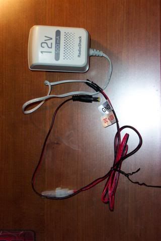
Make sure you get the 12v 500mA version from radio shack though.
Here is a picture
Make sure you get the 12v 500mA version from radio shack though.
skiguy411 said:Make sure you get the 12v 500mA version from radio shack though.
I have the 1500mA as you can see....I’m going to start off and say I’m not an electrician, far from it. Would you happen to know if that extra 1000mA is going to hurt it? Also good job on the cable mod, thought these power supplies had built in protection.
funkymunkey90 said:
I have the 1500mA as you can see....I�m going to start off and say I�m not an electrician, far from it. Would you happen to know if that extra 1000mA is going to hurt it? Also good job on the cable mod, thought these power supplies had built in protection.
Oops, should have put at least the 500 mA verison. Yeah 1500mA should be fine. Im not so sure about the built in protection but hey you can never have enough!
The mA rating of the plug is what it is capable of providing. The actual current (I) is dictated by your supply voltage (V) and the resistive load of your LCD (R) by the relationship
V = I x R or I = V/R
Just because the supply is capable of 1500mA, doesn't mean that is what it will always put out. It should be no problem to use.
V = I x R or I = V/R
Just because the supply is capable of 1500mA, doesn't mean that is what it will always put out. It should be no problem to use.
Hey Funkymunkey90!
Hey Funkymunkey90,
Could you please contact me at: fortymlshot(at)yahoo(dot)com?
I live in Northern Virginia and would like to ask you some questions about your Innovatek 7". Just like everybody else in these forums, I am getting ready to order parts and items needed for my first DIY projector.
Thanks!
Javier
Here is a question to all those out there, who have made a 7" projector, where do you find a 7" fresnel? Can i just buy a bigger fresnel and cut it down to size a little off each side so that the center is still in the middle?
Can i just buy a bigger fresnel and cut it down to size a little off each side so that the center is still in the middle?
Thats exactly what you do buddy 🙂
7" Fresnell
The DIY Projector Comapny store has Fresnell lenses in 7"
http://www.diyprojectorcompany.com/catalog/index.php
I do have a question regarding focal lengths though. I attached a drawing(excuse the crudeness.) Am I right that you want to match the focal length of the Fresnell with the "Effective" focal length of the lens? And the rear focal length ends up being shorter?
If that's how it is, has anyone tried the 80mm lens from DIY Projector Company? Is that 330mm effective length? What is the rear focal length?
Thanks!
Attachments
- Status
- Not open for further replies.
- Home
- General Interest
- Everything Else
- The Moving Image
- DIY Projectors
- 7" projector in 3 months