Hi,
I learned about this whole DIY audio thing only about a month or so ago, so I am very new to the idea and the problems that present themselves in the process. However, in the last month I have done a lot of research on the topic and think that I have come up with an overall layout for an interesting system. Because I’m so new to it though, I would appreciate any additional ideas, criticisms, or information that helps me refine the idea (or completely reject it if it really isn’t that great of an idea). I was trying to come up with an ideal system, but due to money and time constraints (still in college), this is a more long term project. I would like to plan everything out in the mean time though.
The idea is for a pc based 7.1 system that is digital all the way up the actual speaker. This includes a digital crossover. Theoretically, this should eliminate interference in the transmission, allow for per speaker equalization, allow for driver sensitivity matching, have a more accurate crossover, and also have all of the benefits of being computer controlled. I am planning to use 3 way speakers. The down side to this approach is that a lot of DACs and a lot of Amps are used. Also, there might be problems with jitter than need to be worked out.
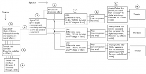
These are my current thoughts on the various parts of the layout. The numbers correspond to the labels on the included diagram.
1.
There are several different possibilities for the sound card interface:
Custom USB interface
2.
This sample rate converter will turn all of the data into 192 kHz format for simplicity sake. This might not be necessary if the Envy24HT already outputs at only 192 kHz. Also serves to attenuate some of the jitter if present (At least I remember reading that sample rate converters did this; If not, let me know). Finding a good sample rate converter will be important, since bad implementations of this can ruin the sound (from what I’ve read the x-fi devotes 70% of its resources to doing this right because it’s so important). I haven’t done enough research on this yet to have specific candidates for the IC. If anyone has had good results with a particular solution, feel free to make suggestions.
3.
I like the sigmaDSP line from Analog devices because of the simplicity of programming. It uses a graphical compiler, so all I have to do is drag and drop components in Sigma Studio to create a biquad filter or any of the other supported blocks. This saves time researching the best implementation of various algorithms let alone having to program them. It should also eliminate most of the debugging. The AD1940/AD1941 supports 8 I2S pins at 24 bit and 192 kHz, so that I can use this to split the signal into 8 distinct channels (only 1 channel per I2S link). I can also use this chip to apply any overall equalization for room correction and the like. It might even be able to do the sample rate conversion if necessary so that I can eliminate block 2. I have contacted Analog Devices to try to get a trial copy of their Sigma Studios compiler to make sure it is able to do everything that I wanted it to do. I hope to hear back from them soon.
4.
The link in the diagram actually symbolizes 8 different links. Each one will go to a different speaker. I was planning to just send the I2S output from the DSP over shielded cat 5e cable to the speakers. I don’t know if this will be a problem or not. If it is, I’ll have to start thinking about using LVDS or another differential signaling method. Blocks 1-3 are single instance while blocks 4-10 are per speaker instance (that is, blocks 4-10 will be replicated 8 times).
5.
I have added in another Sigma DSP here to do digital crossovers, sensitivity matching of the drivers, and any other per speaker correction or equalization. Only 3 channels are necessary at this point, so maybe one of their other models in the Sigma DSP line will be a better fit than the AD1940/AD1941.
6.
I was thinking about doing a complete re-clock at this point. The Sigma DSP can be configured to use an external clock for the serial output. However, I don’t know what happens when the input clock and the output clocks are at slightly different values. Are audio frames dropped or doubled? Anyone know? I might just use another sample rate converter if that becomes a problem. Also, since each clock in each speaker will be running at a very slightly different rate, will the tone shift be audible between the speakers? Or, maybe I’m just being overly paranoid about jitter and it would be just fine without this step? I’m not really sure at this point. Any advice on this part would be helpful. I am also open to completely different methods of jitter management if you know of something that would work better.
7.
I have heard that non delta-sigma DACs sound better. Are there any 24 bit 192 kHz DACs like this? In any case, it needs to be very good sounding (delta-sigma or not), but also relatively inexpensive and uncomplicated as at least 22 of them are going to be needed for a 3 way speaker 7.1 system. Also, a differential output is preferred. I am considering the Wolfson WM8740 DAC for this. I am also considering the TI PCM1792/PCM1794 DACs but I quite honestly don’t know anything about I/V stages at this point (well… other than just using a simple resistor anyways).
8.
I was planning to use chip based amplifiers. Once again, it needs to sound good, be relatively inexpensive, and be fairly uncomplicated as I will need 22 of them. I was thinking that one of the low component count LM3886 designs would be good. I don’t know what’s going on will Tripath, but I was considering one of their amps for the subwoofer (Or maybe I’ll just use a BASH amp). Some of their amps would probably be appropriate for the main speakers too. Also, I was planning to use only one power source for all 3 amps on the speaker.
9.
I don’t know if an extra analog filter is necessary or useful at this point since the crossover is already being done by the dsp. I was thinking there may still be out of band noise that needs to be filtered (from the DAC and amp). I was going to leave the pass band wider than would normally be done on an analog crossover to allow for adjustment with the digital crossover. I don’t know if this step is necessary or not. I’ll probably try it both ways to see if there is a difference.
10.
It’s a 3 way speaker. Not much to say about it. I haven’t decided on a particular design yet.
Thanks for any feedback.
I learned about this whole DIY audio thing only about a month or so ago, so I am very new to the idea and the problems that present themselves in the process. However, in the last month I have done a lot of research on the topic and think that I have come up with an overall layout for an interesting system. Because I’m so new to it though, I would appreciate any additional ideas, criticisms, or information that helps me refine the idea (or completely reject it if it really isn’t that great of an idea). I was trying to come up with an ideal system, but due to money and time constraints (still in college), this is a more long term project. I would like to plan everything out in the mean time though.
The idea is for a pc based 7.1 system that is digital all the way up the actual speaker. This includes a digital crossover. Theoretically, this should eliminate interference in the transmission, allow for per speaker equalization, allow for driver sensitivity matching, have a more accurate crossover, and also have all of the benefits of being computer controlled. I am planning to use 3 way speakers. The down side to this approach is that a lot of DACs and a lot of Amps are used. Also, there might be problems with jitter than need to be worked out.
These are my current thoughts on the various parts of the layout. The numbers correspond to the labels on the included diagram.
1.
There are several different possibilities for the sound card interface:
Custom USB interface
- Needs to be USB 2.0 because 8 channels * 24 bits * 192 kHz = about 40 Mbit/s or 5 MB/s and USB 1.1 only supports 12 Mbit/s.
- Needs to support the USB audio class so that I don’t have to try to write a driver.
- This approach seems a little bit complicated.
- Would need to support 8 channels at 192 kHz.
- Requires conversion to I2S (not sure how to do this).
- Requires expensive sound card/interface.
- Can also be complicated
- Need a way to decode Dolby Digital and DTS. I might not be able to find a way to do this because of licensing issues.
- Dolby Digital only supports 48 kHz sampling, 96 kHz for TrueHD. Only DTS-HD Master Audio supports 24 bit at 192 kHz.
- Need to figure out how to accept SPDIF input.
- Jitter seems to be a problem with anything relating to SPDIF.
- Might be a complicated solution
- Intercept the digital signal on the way to the DAC.
- Already in I2S or similar format. The M-Audio Revolution 7.1 uses the AKM AK4381 and AK4355 DACs (http://www.laaudiofile.com/revolution71.html ) which only support MSB (I assume this is left justified), LSB (I assume this is right justified), or I2S. The via Envy24HT chip only supports I2S and AC-Link that I could find, so it seem that the data going to the DACs would have to be in I2S format.
- Can use an inexpensive sound card such as the M-Audio Revolution 7.1.
- Get all of the benefits of a consumer sound card.
- The Via Envy24HT supports 24 bits at 192 kHz all the way though, but I don’t know if it always outputs data to the DACs at 192 kHz or if it varies (44.1 kHz, 48 kHz, 96 kHz…) depending on differing sources.
- Using a creative x-fi should also be possible.
- Might require precision soldering. The DACs used in the M-Audio are 16 pins and 28 pins. All the pins of interest are right next to each other. The center to center pin spacing seems to be 0.65 mm on both.
- This is my current top choice out of the options unless I’m overlooking something important (or easier).
2.
This sample rate converter will turn all of the data into 192 kHz format for simplicity sake. This might not be necessary if the Envy24HT already outputs at only 192 kHz. Also serves to attenuate some of the jitter if present (At least I remember reading that sample rate converters did this; If not, let me know). Finding a good sample rate converter will be important, since bad implementations of this can ruin the sound (from what I’ve read the x-fi devotes 70% of its resources to doing this right because it’s so important). I haven’t done enough research on this yet to have specific candidates for the IC. If anyone has had good results with a particular solution, feel free to make suggestions.
3.
I like the sigmaDSP line from Analog devices because of the simplicity of programming. It uses a graphical compiler, so all I have to do is drag and drop components in Sigma Studio to create a biquad filter or any of the other supported blocks. This saves time researching the best implementation of various algorithms let alone having to program them. It should also eliminate most of the debugging. The AD1940/AD1941 supports 8 I2S pins at 24 bit and 192 kHz, so that I can use this to split the signal into 8 distinct channels (only 1 channel per I2S link). I can also use this chip to apply any overall equalization for room correction and the like. It might even be able to do the sample rate conversion if necessary so that I can eliminate block 2. I have contacted Analog Devices to try to get a trial copy of their Sigma Studios compiler to make sure it is able to do everything that I wanted it to do. I hope to hear back from them soon.
4.
The link in the diagram actually symbolizes 8 different links. Each one will go to a different speaker. I was planning to just send the I2S output from the DSP over shielded cat 5e cable to the speakers. I don’t know if this will be a problem or not. If it is, I’ll have to start thinking about using LVDS or another differential signaling method. Blocks 1-3 are single instance while blocks 4-10 are per speaker instance (that is, blocks 4-10 will be replicated 8 times).
5.
I have added in another Sigma DSP here to do digital crossovers, sensitivity matching of the drivers, and any other per speaker correction or equalization. Only 3 channels are necessary at this point, so maybe one of their other models in the Sigma DSP line will be a better fit than the AD1940/AD1941.
6.
I was thinking about doing a complete re-clock at this point. The Sigma DSP can be configured to use an external clock for the serial output. However, I don’t know what happens when the input clock and the output clocks are at slightly different values. Are audio frames dropped or doubled? Anyone know? I might just use another sample rate converter if that becomes a problem. Also, since each clock in each speaker will be running at a very slightly different rate, will the tone shift be audible between the speakers? Or, maybe I’m just being overly paranoid about jitter and it would be just fine without this step? I’m not really sure at this point. Any advice on this part would be helpful. I am also open to completely different methods of jitter management if you know of something that would work better.
7.
I have heard that non delta-sigma DACs sound better. Are there any 24 bit 192 kHz DACs like this? In any case, it needs to be very good sounding (delta-sigma or not), but also relatively inexpensive and uncomplicated as at least 22 of them are going to be needed for a 3 way speaker 7.1 system. Also, a differential output is preferred. I am considering the Wolfson WM8740 DAC for this. I am also considering the TI PCM1792/PCM1794 DACs but I quite honestly don’t know anything about I/V stages at this point (well… other than just using a simple resistor anyways).
8.
I was planning to use chip based amplifiers. Once again, it needs to sound good, be relatively inexpensive, and be fairly uncomplicated as I will need 22 of them. I was thinking that one of the low component count LM3886 designs would be good. I don’t know what’s going on will Tripath, but I was considering one of their amps for the subwoofer (Or maybe I’ll just use a BASH amp). Some of their amps would probably be appropriate for the main speakers too. Also, I was planning to use only one power source for all 3 amps on the speaker.
9.
I don’t know if an extra analog filter is necessary or useful at this point since the crossover is already being done by the dsp. I was thinking there may still be out of band noise that needs to be filtered (from the DAC and amp). I was going to leave the pass band wider than would normally be done on an analog crossover to allow for adjustment with the digital crossover. I don’t know if this step is necessary or not. I’ll probably try it both ways to see if there is a difference.
10.
It’s a 3 way speaker. Not much to say about it. I haven’t decided on a particular design yet.
Thanks for any feedback.
Attachments
After doing a little bit of reading (http://www.jitter.de/english/engc_navfr.html), it seems that just using a sample rate converter will not be a very good way to deal with jitter (unless there is a technique that I don't know about). The reason being that some of the jitter is essential sealed into the output signal. This, then, can not be removed later. So, its really important to have low jitter going into and out of the sample rate converter.
The correct way to get rid of jitter would seem to be with phase locked loops or first in first out buffers. I unfortunately know nothing about PLLs, but I have a feeling that it will answer some of the questions that I had about mismatched timing issues on section 6. I guess its time to do more research on this.
Now I'm worried that the sound card might be doing sample rate conversions itself with a jittered clock. I might have to redo their clock if thats the case.
I find this forum to be useful as a place to put all of my thoughts down and consolidate my ideas. I was, however, hoping to get some feed back about my design idea. This really is my first time trying to design something like this, so I would like to know if anyone thinks that its a good idea, bad idea, if its already been done, if it could be done better, or if the difference between this and the way things are normally done would even be noticeable .
Me too
More than two years later. I am considering the same idea.
I've got the revolution sound card and a couple of miniAmps that require i2s input. I've been out of digital electronics for some time so can't contribute much to feasability.
I'm daunted too by the closeness of the adjacent pins on the Envy chip and reluctant to trust my soldering for connection.
I also thought of just getting a decoder chip but am not that keen to make up my own board and my ignorance could give me jitter problem I might have no idea how to get out of.
As an aside; I had been using philips digital amp and then moved to three separate 10w tripath amps running on 12v batteries. Using altec speakers that are very efficient. I blue up one of the tripaths and had to go back to the philips. The tripath are hugely cleaner sounding and this was really confirmed by making the switch back. This seems to me to support the quest for full digital to speakers.
I may have to accept only full digital for the left and right channels but don't want to give up yet. This can get from miniDigi or ministreamer.
How have you got on with the head start you've had?
The philips amp (lx9000r) is somewhat aged so has discrete boards for most activities. I can pick up the i2s from the digital before it goes to the dac fairly easily but it seems such a messy solution and I haven't checked the specs of the chips but they are not likely to be 24bit 192k like the envy.
Volume control is an issue that will arise with any bare bones solution.
Don
- Status
- Not open for further replies.