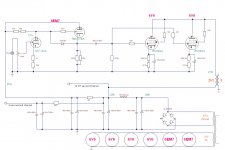
This is my latest project for a while and the next one that I will put into practice, given that I already have everything I need to build it (I will use a pair of OT 2300 instead of 2500, but there won't be much difference). 3 watts are obtained and a distortion around 3% ... as always all the corrections, and suggestions will be welcome before the work begins.
Attachments
Last edited:
Another low voltage tube!
Quick-look comments:
With only ca 213V-25V=+-188V to swing over the OPT, you don't need 2x60mA idle, 75mA total should suffice, plus some headroom, so 80-90mA morte than enough.
EDIT: Actually you probably end up with some 50V over the tube at full current, so the swing over the OPT is only ca +-135V, so definately one tube is enough.
Why the CF? If you intend to drive the grids positive the coupling cap must be a bit larger in value. I think...
Since this most likely will be a flea power amp, go as simple as possible... ditch the CF and maybe even go single bottle on the output. How much more output power do you get with the added complexity and heater power draw in one VS two 6Y6s?
Last edited:
Another low voltage tube!
Quick-look comments:
With only ca 213V-25V=+-188V to swing over the OPT, you don't need 2x60mA idle, 75mA total should suffice, plus some headroom, so 80-90mA morte than enough.
EDIT: Actually you probably end up with some 50V over the tube at full current, so the swing over the OPT is only ca +-135V, so definately one tube is enough.
Why the CF? If you intend to drive the grids positive the coupling cap must be a bit larger in value. I think...
Since this most likely will be a flea power amp, go as simple as possible... ditch the CF and maybe even go single bottle on the output. How much more output power do you get with the added complexity and heater power draw in one VS two 6Y6s?
Thank you for your contribution.
I'll give you a summary of the previous episodes: I already built a SEP 3w with those tubes and I liked it ... I wanted to try to listen to the pentodos playing in triode ... I have 2 other identical tubes, new and selected ... I have a great transformer which can give me 164-176-188v AC without load... with less than 3w I doubt that I can listen to music ... I was advised to use the CF and in general I liked all the components listened in the past that used that configuration ... I have those tubes that, all in one, seem designed for the CF...
if I did the calculations well with all drops on choke and OT, I should have 188v as you wrote ... 6Y6 works with low voltage and high current with max volts rating of 200v.
so you recommend something like 1uf or more?
Last edited:
I think your original cap is good. The CF will charge the cap if you enter grid current and a lrge value will just shift the bias down and give you blocking distortion.
I also tested this ... there must be something wrong because it sounds very low ... the 100k potentiometer raises the volume only up to 1/3 of the stroke ... using a variac, at 50v or 200v it sounds identical .
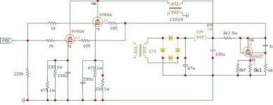
A little further on in the project ... comments and suggestions, as always, are welcome ...
How many volts do you have in the cathode resistors and how many volts are you driving it with? to fully drive the stage you will need the signal input Vpeak to be the same as the cathode voltage this will deliver full power stage swing before blocking distortion hits.
There will be lots of odd distortion before you get into blocking distortion so the max input drive cant be set by ear if you are looking to archive the maximum output without getting into test gear or computer simulations
Last edited:
How many volts do you have in the cathode resistors and how many volts are you driving it with? to fully drive the stage you will need the signal input Vpeak to be the same as the cathode voltage this will deliver full power stage swing before blocking distortion hits.
There will be lots of odd distortion before you get into blocking distortion so the max input drive cant be set by ear if you are looking to archive the maximum output without getting into test gear or computer simulations
I would like to test on the circuit but have not yet been able to figure out how to make the text data on Microcap become file.lib... I need someone to explain it to me because I'm losing my mind...
The correct data should be these:
Attachments
Last edited:
How many volts do you have in the cathode resistors and how many volts are you driving it with? to fully drive the stage you will need the signal input Vpeak to be the same as the cathode voltage this will deliver full power stage swing before blocking distortion hits.
There will be lots of odd distortion before you get into blocking distortion so the max input drive cant be set by ear if you are looking to archive the maximum output without getting into test gear or computer simulations
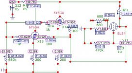
From calculations made manually, if you stay close to a load of 2k6, also recommended by the datasheets, THD settles on a good result of the second harmonic of 8% and of the third of about -2%. I have read that some use OTs more common than 3k5, which however give significantly worse results in the third harmonic.
- Home
- Amplifiers
- Tubes / Valves
- 6Y6 PSET amplifier