Let me start with an apology. The last time I designed and built a tube amp was in 1974, I distill my own gin, and none of those brain cells survive. I will be asking some stupid questions...
My logic for a return to tubes follows:
Keep it simple, class A single ended
Keep it cheep, I will be smoking things in my re-learning curve
This took me to the 26E6 tubes. At less than $5 each I can use a few in parallel to get the power I want and shed no tears when I abuse them.
However when I run the numbers for the output transformer I am perplexed by the results using the following formula
Z = Va^2 / Pa
Where:
Va = Anode voltage.
Pa = Maximum anode dissipation
The normal anode voltage for this tube is only 200V, and the current is 66Ma, so if I run 5 tubes in parallel the output impedance is only 121 Ohms, requiring an output transformer of very low ratio. Are such transformers available? Does the low ratio of turns reduce the problems associated with transformers?
If I take this a bit beyond the logical conclusion and use 10 tubes at only 75 volts the output impedance approaches 8 Ohms, becoming an OTL amp? (adding a cap to block DC).
This is too easy, so what am I missing...
Greg
The plate resistance is not 121 Ohms, but 3.6k Ohms (5 in parallel). But you still need a relatively low primary impedance of ~600 Ohms. For a bit more money, it might be easier to use one of the popular audio power tubes or TV tubes, the OPT would be easier to get.
Hi Greg, it´s not that simple 🙁However when I run the numbers for the output transformer I am perplexed by the results using the following formula
Z = Va^2 / Pa
Where:
Va = Anode voltage.
Pa = Maximum anode dissipation
The normal anode voltage for this tube is only 200V, and the current is 66Ma, so if I run 5 tubes in parallel the output impedance is only 121 Ohms, requiring an output transformer of very low ratio. Are such transformers available?
This is too easy, so what am I missing...
Greg
Your formula is correct to find maximum voltage which can be applied to a resistor dissipating a certain power ; tubes are anything but resistors , besides they are being used in a different way, in this case feeding an inductor/choke (OT primary).
All these differences mean we are dealing with a different problem.
Proper design requires use of tube plate current graphs, available in its datasheet.
Now you know what are they there for 🙂
If datasheet suggests some type of operation, such as "Class A amplifier, one tube, 200V DC supply" , fine, they have already calculated it for you ,including load impedance.
If not, it can still be done, but you need to learn how to do that using published curves.
If you dare ........

If not, which in general is the normal case, go for a known and well studied tube, road will be less bumpy and others can share with you their hands-on experience.
The tube is just one cost element; even if it were free, you still have transformers, chassis, hardware, a coupe extra tubes anyway; in the grand scheme of things you are saving, what, 10-20% (at most) of total cost?.
Check the AX84 community, whether you build one of their projects or not, very useful data and lots of user experience there.
Last edited:
The data sheet gives 6W out with 200volts and 3.6k output transfo.This took me to the 26E6 tubes. At less than $5 each I can use a few in parallel to get the power I want and shed no tears when I abuse them.
If you put 5 tubes in parallel you get 5x6=30W out with a 3.6k/5=720 Ω OPT.
You will be even more perplexed if you see the price tag on those things.However when I run the numbers for the output transformer I am perplexed by the results
Mona
200V at 66mA would be 3k - if it were a resistor. Five in parallel would give 600 ohms, so not sure where you got 121 ohms from. Wait a moment, you did the divide by 5 twice - so 25 in parallel would give you 120 ohms - if it were a resistor.Greg Hyatt said:The normal anode voltage for this tube is only 200V, and the current is 66Ma, so if I run 5 tubes in parallel the output impedance is only 121 Ohms,
A valve is not a resistor.
Thanks for your advice and patience.
I found the formula
Z = Va^2 / Pa
Where:
Va = Anode voltage.
Pa = Maximum anode dissipation
in a text describing the selection of output transformers.
So there are three possibilities:
I picked the wrong text
I am misunderstanding the text
or both
The plate voltage squared divided by the sum of the anodes is
40,000(200 squared) / 330 (66 x 5) = 121
Should I not be summing the current of the 5 anodes?
Did I pick the wrong formula?
I know how to use the plate current graphs for biasing, etc., but not for determination of output transformers. If that is a better approach can anyone provide a link to an explanation?
I have not been able to find the curves for the 26e6, and have been using the curves from older 6L6 tubes which the 26E6 is supposedly a robust version of. Does anyone have a link to plate curves for the 26E6?
I know that I have picked the bumpy road. I always do. I learn more that way.
Greg
> 200V, and the current is 66Ma
200V/0.066A is 3,030 Ohms.
As a first-guess audio load for pentodes, this is a fine start.
Since the data-sheet suggests 3,600, we conclude that 3K would work but some junior engineer ran many tests and liked 3.6K better.
> took me to the 26E6 tubes
O, K. 26E6 appears to be a re-rated ruggedized 25L6. This is a home radio tube, good for a large Watt at 110V (straight off the wall). Since production materials typically ran 300V 450V 600V, 200V even 220V was allowed (I've seen more on 25L6).
The ~~200V zone is awkward, since it is higher than you get from a 120V winding, but much lower than most of the still-available high-voltage transformers.
> 5 tubes in parallel
Single-ended is problematic, tolerable in very small amps or for high-buck statement amps. If you are gonna run more than one, you should really consider push-pull. Audio IS push-pull. If your tubes only pull, then the output transformer must store magnetic flux from one half-cycle to the next. It is significantly larger (more expensive) than a push-pull OT of the same power output. A single-ended output for *330* mA, even at a custom 700r impedance, will be extremely large.
The 26.5V heater is awkward, alone and in combination with whatever 6V/12V tubes you use to drive it.
> Keep it cheep
Then look at guitar-amp parts and designs. They are in large production, prices are competitive. A "Fender DeLuxe" transformer set will do around 20 Watts and with a hi-fi driver and NFB the hi-fi performance will be fine. 6V6 cost more than 26E6 but the savings on iron and funny voltages makes it up.
6Y6 looks to be identical to the 26E6 (except no plate cap and a 6.3V htr) and has curves here:
http://tubedata.milbert.com/sheets/093/6/6Y6GT.pdf
Can get 6Y6 for $3 here:
Electron Tube List range 6K4 - 6ZY5G - Vacuum Tubes @ ESRC Vacuum Tubes
For SE operation, why not get something decent (only need 1 tube and just $5) that has been popular for building SE amps:
http://tubedata.milbert.com/sheets/137/6/6CB5.pdf
I appreciate the generous sharing of knowledge and wisdom!
Yes, the 25L6 is very close, and the 6Y6 is identical.
At some point in the future I will start another thread which will explain my fondness for the 26E6. I have three hot-rod flatheads from the 1920s-1940s which I modify as those at the time could have, even if they did not. So I have started work on tube logic for fuel injection using components available at the time. I already have 24V in the rods for dash instruments which I source from old war-birds (all 24V). So a tube that can withstand 600G and operate on the 24V system is attractive (any other alternatives I should consider?). I was trying to use the same tube for the fuel injection, hi-fi, and another project for a guitar amp. Perhaps this was a step too far and I need to use different tubes for each application!
Any favorite circuits for 6Y6 push-pull?
The ~~200V zone is awkward, since it is higher than you get from a 120V winding, but much lower than most of the still-available high-voltage transformers.
In my last project, I used a 40V dual-secondary power transformer with those windings connected in series to a full wave doubler, which yielded 200VDC after a few volts loss in filtering.
The GE curves previously posted provide harmonic distortion relative to load. The Tung-Sol curve below breaks the distortion into its components of 2nd harmonic and 3 harmonic.
https://frank.pocnet.net/sheets/127/6/6Y6GA.pdf
Note that Eb is 200V in the GE curve, and 135V in the Tung-Sol curve so some extrapolation is required to compare them.
A subtle change in load (from 1500 Ohms to 1800 Ohms) roughly doubles 3nd harmonic distortion while halving 2nd harmonic distortion. This should provide a much more dramatic change in tone color than changing other variables, such as tube rolling. Most folks seem to prefer even harmonic distortion to odd, so it might be desired to compromise total distortion to bias even over odd. Given the cost of OT rolling, and that a Variac is noisy (and provide no taps for UL), has anyone inserted resistors to tune the output load? Are there other techniques?
Resistance is not the same as impedance, so it's no good to use resistors to "tune' the load. Instead you can try varying the bias point and/or changing the actual load, i.e., different speakers or different taps on the OPT.
Perhaps the title of the thread should be changed... There is nothing deviant about the OPT, and OTL is hardly a good option.
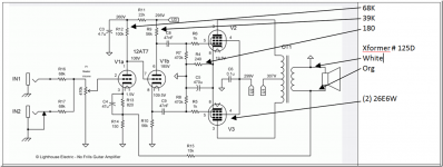
The Hammond 125D Output Transformer (10 Watt, only 150 HZ to 15KHz, $38) has different taps for selecting the impedance ratio. I can't figure out what taps the orange and white wires refer to in the above schematic though. The 125D has numbered terminals, not wires. A P-P design shouldn't have any 2nd Harmonic if adjusted correctly.
26E6 is similar (except for grid2 V) to a 6BQ5, so probably around an 8K OT for class AB P-P.
Hammond 125D: http://www.mouser.com/ds/2/177/5c0054-77730.pdf
http://tubedata.milbert.com/sheets/093/6/6BQ5.pdf
11 to 17 Watts out depending on B+.
A better P-P OT than the 125D would likely sound better:
40 Hz to 18 KHz:
http://www.edcorusa.com/gxpp10-8k
http://www.edcorusa.com/gxpp15-8k
20 Hz to 20 KHz:
http://www.edcorusa.com/cxpp10-8k
http://www.edcorusa.com/cxpp25-8k
Late edit to above post:
Looks like 26E6 is capable of more current than the 6BQ5, DCmax more like 90 or 100 mA, versus 65 mA for the 6BQ5. So the OT primary impedances should be more like 5K or 6K likely (if sticking to the 200V B+ max spec). But if going with the spec busting 300V B+, then an 8K Ohm primary.
George (Tubelab) has gotten spec busting Watts out of the 26E6 at 300V with a 6600 Ohm OT, take a look here:
George RE: 26E6WG
Last edited:
Those would probably be late 6BQ6GA's, with 6JN6/6GE5/6GV5 guts. (all 17.5 Watters, versus 12.5 Watts Pdiss for the 26E6)
For $4, just get a 6HJ5 or 21LG6 (75 to 100 Watts output), $1 21HB5 or 6GB5 not to shabby either, or $5 6CB5.
For $4, just get a 6HJ5 or 21LG6 (75 to 100 Watts output), $1 21HB5 or 6GB5 not to shabby either, or $5 6CB5.
Last edited:
> fuel injection using components available at the time
Fuel injection was widely used in fighter airplanes from mid-WWII. Helps with icing and dogfighting. These systems were pneumo-mechanical, and not so different from the 1957 Corvette (except in scale and layout).
No doubt you know the Hilborn, good flat-out but hard to drive in traffic. Ha, they are still in business!
A vacuum-tube injection controller is hardly absurd, or impossibly difficult. The real key will be to minimize the number of tubes, because even with ruggedized tubes this will dominate MTBF and walk-homes. (I'd keep a Holley 2bbl on a stub for instant change-over.)
- Status
- Not open for further replies.
- Home
- Amplifiers
- Tubes / Valves
- 6Y6/26E6 PSE Amplifer