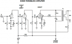
Hi there! I am in the final part ordering stage for a pair of single ended 6v6 monoblocks that I am building. The circuit comes from EJ Jurich's book, "Vacuum Tube Amplifier Basics"
Circuit schematic for input stage GIF is attached. I think. Question is this: I will be controlling the volume of the two monoblocks with a Mezmerize DCB1 preamp buffer. The circuit schematic also calls for a volume pot on the input. Should I leave the pot in place on the monoblck, set it at some arbitrary point, then control the volume of the two with the preamp? Or should/can I omit the volume pot on the monoblocks all together and just use the preamp to control levels?
If I do leave the volume pots off the monoblocks, do I need to put anything in their place? Or just omit? Thanks!
-Corey
Attachments

Hi, There are a number of options. The easiest since you have a preamp is to simply replace the pots in the amps with fixed resistors of the same value.
You can leave the pots there and use them as level controls. This might be helpful if your preamp has too much gain and you find the volume settings on it to be near the zero end and difficult to set. Also if you leave the pots in place you can use them as balance controls if the preamp doesn't have that feature. My personal choice would be to replace them with the fixed resistors as it eliminates a potential source of problems....pots tend to become noisy after a while. Save a few dollars on the build as well.
EDIT: looking at the schematic again....you could depending on the value of R2 just eliminate the pot and not put a resistor in its place. My personal thought would be to get rid of C1 as well. The capacitor is for blocking dc that might be on the output of something like the preamp. Virtually all such devices no longer have this as an issue. The DC if present would upset the gain of the first stage of the amp. It has been a long time since I have seen a well designed preamp have any DC on the output. While not a minimalist I avoid adding any component that is not needed as it will in some way (sometimes very subtly) alter the sound. Just my 2 cents.
Last edited:
Hi Corey,
Leave the input capacitor in the circuit!
As Bruce suggested, you could figure out how sensitive you want your mono block to be and put a resistive divider in there. Otherwise just put a 100K resistor to common from the input jack. This will drain any charge from the input capacitor that might build up.
If you might change input cables with the system running, you can either use a control or a switch to mute the input. There's nothing worse than a healthy blast of hum to make everyone jump.
-Chris
Last edited:
Please, please, build with 12BH7s.  The 12AU7 is non-linear and (IMO) should not be used in the voltage amplification role.
The 12AU7 is non-linear and (IMO) should not be used in the voltage amplification role.Hi Corey,
Just to confuse you a little more 😀
6V6SE Stereo Amplifier Experiment
Here is his newer version. A bit more involved but perhaps a technical improvement.
Andrew
Just to confuse you a little more 😀
6V6SE Stereo Amplifier Experiment
Here is his newer version. A bit more involved but perhaps a technical improvement.
Andrew
A few things to think about:
1- The circuit inverts phase from input to output, so consider your preamp's output phase and also the possibility of wiring the speakers out of phase to ensure you have correct phase in the system.
2- using any of the tubes shown (12AU7, 12BH7 or 6SN7) in a cascaded design will result in a fair amount of gain, 40dB of voltage gain could easily be the case. As the 6V6 is not particularly difficult to drive, expect a lot of gain from this circuit.
3- In his last circuit (the only one shown with values), he has the feedback set for unity gain (between the driver and output stages), meaning a large amount of feedback. In general, most look to limit the amount of feedback in designs. This will reduce overall gain significantly, but the audible results of too much negative feedback may result in poor sound quality overall.
Regards, KM
Everyone!! Thanks so so much for the valuable input. I'll let you know when I get the thing built. Appreciate input!
-Corey
-Corey
Hi Corey,
Leave the input capacitor in the circuit!
Just curious - why?
Please, please, build with 12BH7s.
This ^^^ 12BH7 is ridiculously More Linear/Dynamic/Detailed sounding than 12au7s.
Member
Joined 2009
Paid Member
40dB of voltage gain could easily be the case.
Could C5 (cathode bypass of the 6V6) be removed to reduce gain or does this increase the effective plate resistance too much and kill the bass ?
EDIT: what the heck was I thinking - better idea altogether - strap the 6V6 in triode mode instead of ultra-linear. Better drive, lower gain, better sound perhaps.
Last edited:
This is awesome ya'll. Bigun-- I am a total rookie, having just assembled one kit amp (decware zen kit) and read through most of Mr. Jurich's book. I'm afraid I don't know what you mean by strap the 6v6 in triode vs ultra linear. I have seem amps that have a switch to switch between the two modes. Is this complicated? When you have some time (no rush) would you be able to bang out a schematic? I've no idea if this is a big ask or not so if it is, feel free to ignore. Also no rush.
I think what I will do for now is build the circuit as is, then listen to it, then perhaps make the changes suggested above, maybe remove the volume pot or the input cap and listen again. Afterall, that's the fun of what we do, right?
Last question... Suggestions on 12BH7? I do have some conn (re-badged RCA clear tops) that I plan on using first, but then rolling the 12BH7 in. I've seen some, but a suggestion on reasonably (20-30 ish per pair) would be appreciated.
Thank ya'll SO MUCH!
-Corey
jdarg; said:Originally Posted by anatech
Hi Corey,
Leave the input capacitor in the circuit!
Why? If the source is passing enough DC to upset the bias, it is poorly designed or broken IMHO.
In designs with a GNFB loop, like that under discussion, actions to protect the O/P transformer's core from saturation due to a huge LF error correction signal are in order. The I/P cap. combines with the voltage amplifier's grid to ground resistor to form a high pass filter, which blocks LF trouble makers. When the O/P trafo is 1st rate, place the pole in the 15 to 17 Hz. range. When the O/P "iron" is mediocre, sacrifice part or all of the 1st octave. Remember, very little musical content lies below 41 Hz., which is the lowest fundamental a "standard" double bass produces.
- Status
- Not open for further replies.
- Home
- Amplifiers
- Tubes / Valves
- 6V6 Single Ended question