Instead of an "ordinary" 5Y3, spend a little extra and buy a 6087/5Y3WGTB. The 6087 has a cathode sleeve. The IDH signal tubes will last longer with a slow B+ rise. Prevent cathode stripping.
A 5V4 is another suitable 1/2 indirectly heated rectifier. The forward voltage drop in a 5V4 is less than that in a 5Y3.
A 5V4 is another suitable 1/2 indirectly heated rectifier. The forward voltage drop in a 5V4 is less than that in a 5Y3.
Eli Duttman said:Instead of an "ordinary" 5Y3, spend a little extra and buy a 6087/5Y3WGTB. The 6087 has a cathode sleeve. The IDH signal tubes will last longer with a slow B+ rise. Prevent cathode stripping.
A 5V4 is another suitable 1/2 indirectly heated rectifier. The forward voltage drop in a 5V4 is less than that in a 5Y3.
Eli Duttman,
do i have to change the values of the any of the parts in the power supply should i use 5Y3WGTB rather than 5y3 only?
i am not Eli but i would say no. am i right Eli? 😀 and i'd say go for slow start rectifiers, or put in a stand by switch (which is mostly what i do). you don't have to limit your tube rectifier choices, find one that is slow start and which you will have a budget for, because 5AR4's are ridiculously high priced in the philippines. 5Y3 and a stand by switch a lot cheaper 😀 😀 😀
once you have sorted out your choice, then we can design the PSU around that using PSUD. 😉
once you have sorted out your choice, then we can design the PSU around that using PSUD. 😉
6087/5Y3WGTB replaces an "ordinary" 5Y3 without any circuit changes. Same story for the 6106. A 5Y3 with a slow B+ rise is nice. I use Raytheon 6087s in my DECWEAR SE84Bs, whose circuitry is also triode/triode strapped pentode.
If you use a 5V4, you will have to allow for a higher B+ rail voltage.
A way to get the slow B+ rise CHEAP is to use 2X 7Y4 Locktal tubes. In the US, Locktal sockets cost more than 7Y4s and 7Z4s do.
If you use a 5V4, you will have to allow for a higher B+ rail voltage.
A way to get the slow B+ rise CHEAP is to use 2X 7Y4 Locktal tubes. In the US, Locktal sockets cost more than 7Y4s and 7Z4s do.
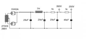
Lico said:The first schematic planet10 posted is the one i built. here's the ps for it. Enjoy.
Andy
You may want to re-think that, the 5V4 is rated for 10uF max for the first stage of a cap input filter...
Peace
^^ Not according to the data I have... 32uF is the max input capacitance. 10uF is suggested, but you can use more as long as you don't go over peak current ratings. I would suggest something like 22uF for a 5V4.
Check this:
http://www.mif.pg.gda.pl/homepages/frank/short/001/5/5V4.gif
I use a Mullard GZ32, the nicest rectifier around! It is a 5V4 equiv.
Check this:
http://www.mif.pg.gda.pl/homepages/frank/short/001/5/5V4.gif
I use a Mullard GZ32, the nicest rectifier around! It is a 5V4 equiv.
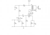
This is the Schematic of my SE EL84 amp. You will have to change the biasing of the output stage a little to use a 6V6 but everthing else should be the same. I'm king of busy today otherwise I would do the calculations for you and post them. Sorry.
Attachments
i decided to go for a 5u4g rectifier. i'll be using a power transformer rated at 300-0-300. can anyone please help me design the power supply if i require 250V B+ for the 6V6 and 180V for the 6sn7 driver. thanks
A choke I/P filter should put you quite close to 250 VDC. The rectifier feeds a LC section plus bleeder resistor. Follow the 1st LC section with 2X LC sections, 1/channel for good separation. A RC section for each driver plate finishes things off.
Eli Duttman said:A choke I/P filter should put you quite close to 250 VDC. The rectifier feeds a LC section plus bleeder resistor. Follow the 1st LC section with 2X LC sections, 1/channel for good separation. A RC section for each driver plate finishes things off.
thanks eli. but as a newbie (please pardon my ignorance), i cant quite understand what you've just mentioned. i would really appreciate if you could put it in schematic form.
camotecue,
you said you need a voltage drop of 70V (250-180) and we need the current drain of that stage to compute for the dropping resistor.
if it is 2mA for example, then R = 70V / 0.002A = 35Kohm
i can draw you a schematic as suggested by eli, later.
we will also need the current drain of the power stage to compute for the power supply.
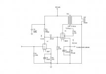
here is the schematic.... it does not include the RC section which would be B+ (from the diagram) ---R (?)--- C (47uF) ---> driver for each channel... oh and i forgot the bleeder on the first cap
you said you need a voltage drop of 70V (250-180) and we need the current drain of that stage to compute for the dropping resistor.
if it is 2mA for example, then R = 70V / 0.002A = 35Kohm
i can draw you a schematic as suggested by eli, later.
we will also need the current drain of the power stage to compute for the power supply.
here is the schematic.... it does not include the RC section which would be B+ (from the diagram) ---R (?)--- C (47uF) ---> driver for each channel... oh and i forgot the bleeder on the first cap
Attachments
arnoldc said:camotecue,
you said you need a voltage drop of 70V (250-180) and we need the current drain of that stage to compute for the dropping resistor.
if it is 2mA for example, then R = 70V / 0.002A = 35Kohm
i can draw you a schematic as suggested by eli, later.
we will also need the current drain of the power stage to compute for the power supply.
here is the schematic.... it does not include the RC section which would be B+ (from the diagram) ---R (?)--- C (47uF) ---> driver for each channel... oh and i forgot the bleeder on the first cap
thanks for your help. do i see three (3) 10H chokes?
yes, you do. the value (10H) is a suggestion and what i mostly use. the 5U4G manual also lists that as a typical value if i'm not mistaken.
Better than 3 10 H. chokes is a 20 H. choke in the 1st position and 2X 5 H. in the 2nd position. A 10 KOhm bleeder resistor is used with a 10 H. choke, while a 20 KOhm bleeder resistor is used with a 20 H. choke. A larger 1st inductor allows you to lower the I^2R losses (heat) in the bleeder resistor.
BTW, an inductor rated for choke I/P service is required in the 1st position. "Beefy" construction is in order to cope with the large AC ripple current that is present. The chokes used in the 2nd position can be of the "ordinary" variety.
BTW, an inductor rated for choke I/P service is required in the 1st position. "Beefy" construction is in order to cope with the large AC ripple current that is present. The chokes used in the 2nd position can be of the "ordinary" variety.
Or you could just use something like 20uF-10H-47uF and you would be right. Modelling this in PSUD gives a very smooth power supply.
Voltage would be higher, at around 320V, but you can boost your cathode resistors on the 6V6s to compensate, so you don't go over the plate dissipation rating (12W I think?)
Three chokes is excessive, IMHO. 🙂
Voltage would be higher, at around 320V, but you can boost your cathode resistors on the 6V6s to compensate, so you don't go over the plate dissipation rating (12W I think?)
Three chokes is excessive, IMHO. 🙂
Three chokes is excessive, IMHO.
You're going against long established precedent. Older editions of the ARRL Handbook specifically advise that 2 LC sections in cascade be used when choke I/P filtration is employed.
Using a pair a LC sections after the 1st LC section isolates the 2 channels from each other. It's a form of pseudo dual mono power supplies.
CLC supplies are POORLY regulated, while choke I/P supplies are WELL regulated. Another advantage of choke I/P filtration is the ability to access the full VA capability of the power trafo.
- Status
- Not open for further replies.
- Home
- Amplifiers
- Tubes / Valves
- 6V6 SET amp with 6SN7 driver