hi poinz,
ill try changing the pot on the lightspeed. im still waiting for the pcb of the lightspeed so can put it inside the amp.
thanks poinz.
ill try changing the pot on the lightspeed. im still waiting for the pcb of the lightspeed so can put it inside the amp.
thanks poinz.
I wouldn't think you would hear the pot at all in a lightspeed, strange. All the pot is doing is varying the intensity of the LED's to the LDR's, it really isn't in the signal path at all. Maybe you are hearing some noise as the LDR's shift their resistance?
Cheers
James
edit: Well I guess maybe if the pot is rough.(?) Though I have seen people using those el cheapo duals from the Shack and they seem to work fine.
Cheers
James
edit: Well I guess maybe if the pot is rough.(?) Though I have seen people using those el cheapo duals from the Shack and they seem to work fine.
Last edited:
What you hear in a scratchy pot is electrical noise; microarcing, probably. Electrical noise in the pot will be electrical noise in the the LDRs, and they turn electricity into resistance. I would bet you'll hear it.
Aloha,
Poinz
AudioTropic
Aloha,
Poinz
AudioTropic
Hmmm.... Interesting point, I hadn't thought about that. Though I would say that if you are going to spend the money for a very good pot for the LS, just lose it all together and stick the very good pot right in the Machine.
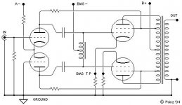
BTW, I don't want to jack, but I had wanted to ask Poinz a question. A while back I pulled a layout of a Machine-esk amp off of an E-Linear discussion thread over at AA. Instead of grid resistors it used a center tapped grid choke. Has this ever been tried on the Machine, or is the cost / space not really worth it?
......digging......... HA! Found it!
Cheers
James
Attachments
Last edited:
I can promise you it hasn't been tried by me. That's my drawing; I'll have to go look at what I was thinking of in '04. Off the top o' me noggin, I have no idea.
P
P
HAHA, no worries. I assumed it was yours, but of course it could just be a re-draw. I dug a bit at AA and couldn't find anything, just the pic I had saved on my computer. I was just interested because I am trying to learn a lot about the Musical Machine as I am wrapped up in a nearing-two-year venture into a build of one. Of course I would never build one Ultralinear or E-Linear, don't need the power or the feedback. I am just always interested in all of your little snip-its of knowledge dropped about that beautiful amplifier.
This one just had me thinking a bit, and I figured that as long as I had you here... The problem I saw with it was I wasn't sure if one would really gain much versus the use of premium space underneath. Don't scratch the ol' noggin to hard, no worries 😛

James
This one just had me thinking a bit, and I figured that as long as I had you here... The problem I saw with it was I wasn't sure if one would really gain much versus the use of premium space underneath. Don't scratch the ol' noggin to hard, no worries 😛
James
Looking at that image again, I see that it emerges from a conversation I was having with Doug awhile back about his partial feedback setup, E-Linear. I nominally don't agree with this technique myself, since it looks like a solution to a non-problem (the subcircuit between the output of the driver and the output of the power device being the most naturally linear part of the circuit), but he reported good results with it and can undoubtedly explain its mechanisms to you far better. You might ping him here and on AA as PakProtector.
Aloha,
Poinz
AudioTropic
Aloha,
Poinz
AudioTropic
I realise that this is an old post, but I have just finished the 6V6 version, and it sounds checkt!
However, in my pursuit of being me, I want to build the EL34 version as I have some NOS tubes, and I cannot keep building amps so my wife has said.
Anyway my question is about the 6GK5, do I use 2 per channel as the schematic shows 1,7 connected together.
I am not even a novice at this, I have a career as a Geo-Technical engineer, and some good books, so I have the maths ok, but not the talents of you guys.
Any help would be humbling for me.
Tack
Björn
...the 6GK5, do I use 2 per channel as the schematic shows 1,7 connected together....
Read the 6GK5 datasheet. Does that clear up your question?
If you look at the 1st posts schematic the tubes are all properly numbered at their connections so you don't really have to look at the data sheet in most cases. Any schematic can have errors so likely a really smart idea.
As the numbers are the same for each tube you should take it to mean that yes you need 2 of those driver tubes /channel.
If it was a tube with dual plates like a 12AT7 , 12AU7 , 6922 etc. the numbers to the plates/cathodes and screens(grids) on the tube would all be different. With that type of tube then you would only require one per channel as they are 2 tubes in one!
The filament connections would stay the same though so their numbers wouldn't change.
Last edited:
Thank you
Thank you guys for that.
Just one more question then if that is ok, I have some 12AU7 tubes, mid gain I think which is ok for me, I am happy with the depletion mosfet, so the question is 2 fold I guess,
Can I or is it feasible to use the 12AU7 with this design,
Will I need to change the negative voltage to the original design to can I use the -66 with the fet?
I am not stuck on this idea and if the general consensus is it will sound better 6GK5 then I will get them, 7 pin package so I will need to change and add some sockets but that is just more experience for me.
Björn
Gain will be about 1/3rd with the 12AU7. (This is in the datasheets too.)
You will need a much bigger signal from your preamp/source.
Work? Yes. Work happy? Maybe not.
12AT7 would be a closer fit.
You will need a much bigger signal from your preamp/source.
Work? Yes. Work happy? Maybe not.
12AT7 would be a closer fit.
Never, ever, the 12AU7/ECC82 in a voltage amplification role. The type is non-linear. 😡 
Early on in "Musical Machine" development, Poindexter used the 5965 in the splitter/driver role. The 12AV7 is close to the 5965 and a CCS in the LTP's tail should make that type satisfactory. Remember, a CCS in the tail of a LTP forces symmetry between the 2 triodes.
Early on in "Musical Machine" development, Poindexter used the 5965 in the splitter/driver role. The 12AV7 is close to the 5965 and a CCS in the LTP's tail should make that type satisfactory. Remember, a CCS in the tail of a LTP forces symmetry between the 2 triodes.

Guys thank you!
You have all been fast and friendly, if you ever need a tunnel, foundations designed or a basement I will happily help with the calcs!
Tack
Björn
You have all been fast and friendly, if you ever need a tunnel, foundations designed or a basement I will happily help with the calcs!
Tack
Björn
Poindexter,
Going back to your Post # 13 . . .
Diodes from screen voltage to the screen? ? ?
If you do not want any screen signal to get on the plate, why is the circuit shown wired as a Triode connected beam power tube? Whenever the screen current changes (up or down) it puts screen signal on the plate. If the control grid changes voltage, the screen current changes (unless the screen voltage is so low that the screen current is zero, or unless the control grid has the tube into cutoff). In those cases, there will not be very much usable plate current either.
One way to keep the screen signal off the plate is called Beam Power mode, or in the case of a Pentode, Pentode mode, using a regulated screen supply.
The idea of using a Triode wired Beam Power tube is to get the plate resistance, rp, down; but it also causes the the tube voltage gain to go down. It has a voltage gain about the same as the control grid to screen grid mu (u). The resultant gain is: (u x (RL/(RL + rp))).
And for the Heart of my Question: I still have not seen any explanation of Triode Wired Beam Power tubes, that need to use a diode in series with the screen grid stopper resistor. If you need less voltage on such a screen, just use a larger grid stopper resistance, or if you need lower voltage and a lower impedance to the screen, then use a Zener diode plus the grid stopper resistor (and be sure there is always enough screen current to keep the zener in the zener voltage region). Otherwise, you will have large discontinuities at large signal conditions, and that sounds terrible (except for an overdriven guitar amp?).
Last edited:
Hello Hello!
So I have finished the build but not without problems.
I the 6GK5 tubes are working great, I have a very good preamp stage, the problem is with the power tubes, and the fact that I have never used tube rec before.
So, I think I may have blown my OPT which is not major, they are 5k but 12w, that is not how I blew them however, it was incompetence on my part that did that trick.
Back to business, the plate voltage to the 6gk5 when loaded is 1v, if I remove the tube I get around 150v, why would this be?
Also, the 30ohm resistor are burning out, I have 2w in there and still, this only happens when I connect the B+ so I think it is bad OPT.
Just a general steer would be great, the 6V6 worked for me first time, I know it is something I have done wrong, I am just out of answers now, I have checked my grounding, started at reservoir resistor and worked around as per schematic to input, it is smooth with everything running to the red/yel grn/yel 0V.
PS: I have Morgan Jones book, it has been really helpful, but I cannot work it out, I can put some screen shots from my scope, but it will be nothing of use I do not think.
Tack
Bjorn
Hopefully some experts will drop in soon with good troubleshooting strategies. This is a one-channel (monoblock) amp? Or stereo? Have you double checked the wiring on the tube sockets?Back to business, the plate voltage to the 6gk5 when loaded is 1v, if I remove the tube I get around 150v, why would this be?
Also, the 30ohm resistor are burning out, I have 2w in there and still, this only happens when I connect the B+ so I think it is bad OPT.
(You know that they are numbered looking at the bottom of the socket).
Have you tried different tubes? Which resistor is burning? Can you post the schematic you are using?
My first guess would not be the output transformer.
Attachments
So....
Turns out it was a failed bit of insulation on the 8ohm speaker output, it was shorting to ground and that was that!
I have not had the chance to do a lot been busy with work, however turned it on today, warmed her up, and applied a signal, which is very week at the output.
So, I plugged a sound source and played some music, although it sounds very responsive, the volume was very low, even with the 100k pot turned up full!
I have checked the bias voltage, the CCS on the LTP and the plate voltage, all seem nominal, in fact my B+ voltage is spot in, 320v feed to the 5gk5 plate is around 310, then 133v at the TP on the schematic that shows 135v.
Any pointers would be great!
I checked my grounds again, they are exactly as the Schematic.
I have used 22AWG from the 5AR4 to the 1st Res Cap and from the CT on the PT Red/Yel Grn/Yel, could that be too much resistance on the cable? Would a bigger gauge cable make a difference, it does not get hot however so watts are good?!?
UPDATE!
So, I put the 6GK5 on the scope to see the signal, CH1, and CH2 on the 8OHM out, the waves are the same, identical, there is no amplification through the EL34, but the 6GK5 are, if I put the scope on the 2 6GK5 the phase inverter is working, I am just confused, I know this is probably frustrating for you guys having to answer such basic questions, I just have no idea and no quit!
Tack
Björn
> on the 8OHM out, the waves are the same, identical, there is no amplification through the EL34
It is typical for the power tube and speaker transformer together to have a gain of less than unity.
Elsewhere we are hitting on a Champ; the gain from 6V6 grid to 4 Ohm load is maybe 0.3 (the other guy says, I suspect less).
> I plugged a sound source .....the volume was very low, even with the 100k pot turned up full!
1 Volt peak should slam this to full output, which would be loud.
What is "a sound source"?? Many cellphones will not get near 1V.
- Home
- Amplifiers
- Tubes / Valves
- 6v6 music machine build help!