Hi,
Is the 6v6 still the preamp to go for? I'm building the P.millett uniamp as my first go on tubes. As some of you know I will use my hotrodded Dcb1 as volume controll and buffer to start with. This is mated with Salas mezmerized like source control. So the second step is to maybe replace the Dcb1 with something else. Is best advice to use the 6v6 preamp or something completely different?
Regards
For choosing a pre for your application first things to analyze is from what dB level to what dB level you would like your preamp to amplify. Then output impedance requirements derived from your power amps input impedance.
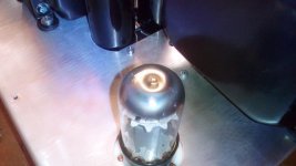
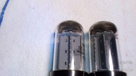
Puddle in glass on the top of the rectifier tube, is problem;
I ask this because not remember the state in the tube initially.
I ask this because not remember the state in the tube initially.
Attachments
Last edited:
The Uniamp doesn't seem to need a pre.The dcb1 should be enough. I believe I'll build the 6V6 as a buffer if I get the itch 🙂
Regards
Regards
I planed to build this preamp. And my PSU will look like this:
Transformer -> SS diodes -> 220uf - 220R - 220u -> salas SSHV2 -> two channel
But I have a question about the transformer, I have to go for custom-made service for the transformer, could anyone confirm for me this specs is ok? I need it to be right before pass it to ....
280VAC -> 390VDC - 15.4VDC (70mA through 220R) - 20V (DN2540 vol drop) = 354V DC (so I have some margin to bring it down to 340V).
IN: 220V
OUT:
0-280V/290V 200mA
0-10V 1A
0-10 1A
Thanks!
Last edited:

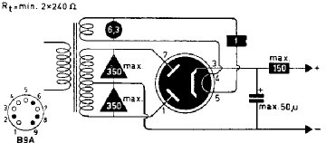
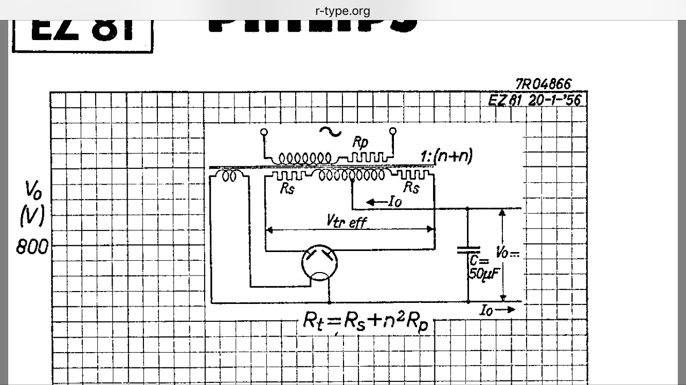
I would say R total. Here is an example from the EZ81 datasheet what Rt is.
ez81 pin 3 just for output of voltage .but in Philips data ez81 like 5u4 !!!
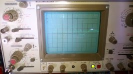
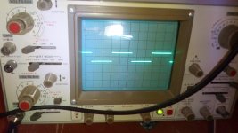
Output spikes ?
Any sugestion?
Put a resistor instead of the tube and see if its yer PSU. Ohms law R= tubes drop / current. 20 K ish 10 W
Output spikes ?
Any sugestion?
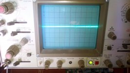
I believe its a measurement loop thing. Common mode noise picked by the chassis and tubes. Try again with the power off and it will probably be the same.
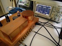
I tried for you on my 6V6 preamp and it was the same spikes at 10mV scope setting as they were with power off and again the same even with the generator disconnected and the preamp's power plug pulled out completely!
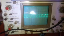
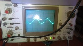
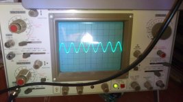
Just check you got about 180kHz -3dB bandwidth for the cathode follower circuit at 3/4 open 50K log (output=half the input) and about 2uS rise time for 10kHz square at same pot's position. Or about 80nS for 1kHz square and the pot fully open. Have no fuzzy sinewave output also from max to minimum when at 200-500mV scope's vertical and 1-2VRMS sinewave input. If those checks prove good you should be all set.
Attachments

Put a resistor instead of the tube and see if its yer PSU. Ohms law R= tubes drop / current. 20 K ish 10 W
Thanks for your help Stajo.🙂
with resistor i dont have any spike.
I believe its a measurement loop thing. Common mode noise picked by the chassis and tubes. Try again with the power off and it will probably be the same.
I tried for you on my 6V6 preamp and it was the same spikes at 10mV scope setting as they were with power off and again the same even with the generator disconnected and the preamp's power plug pulled out completely!
Just check you got about 180kHz -3dB bandwidth for the cathode follower circuit at 3/4 open 50K log (output=half the input) and about 2uS rise time for 10kHz square at same pot's position. Or about 80nS for 1kHz square and the pot fully open. Have no fuzzy sinewave output also from max to minimum when at 200-500mV scope's vertical and 1-2VRMS sinewave input. If those checks prove good you should be all set.
THANKS for ALL Nick, 🙂
i will do all the above test.
By the way, those bandwidth and risetime numbers were with Russian smoked glass NOS 6П6С so your results may vary a little with other valves and your wire up. Same value pot (50k log) and position should be the most decisive likeness factor though. At max you should have 10% signal loss in the buffer with any pot anyway.
I planed to build this preamp. And my PSU will look like this:
Transformer -> SS diodes -> 220uf - 220R - 220u -> salas SSHV2 -> two channel
But I have a question about the transformer, I have to go for custom-made service for the transformer, could anyone confirm for me this specs is ok? I need it to be right before pass it to ....
280VAC -> 390VDC - 15.4VDC (70mA through 220R) - 20V (DN2540 vol drop) = 354V DC (so I have some margin to bring it down to 340V).
IN: 220V
OUT:
0-280V/290V 200mA
0-10V 1A
0-10 1A
Thanks!
265V secondary would be more in range I think. Q1 does not drop more than 2V. The in-out drop is a matter of raw DC level vs your output setting. Also use 68k 5W bleeder across the last reservoir capacitor, and a 3A 40V Schottky diode instead of Zener for D3. So to have a safer PSU. Consider IXYS IXTP08N100D2 for Q1 also as it is 1000V 800mA because the raw DC is near 400V that the DN2540 has spec for and there could be MOSFET killer on/off transient HV peaks. Q2 will not see HV, only the VGS of Q1. Use good sinking and isolation because about 30mA spare current at 340V is 10W dissipation for the IRF840.
265V secondary would be more in range I think. Q1 does not drop more than 2V. The in-out drop is a matter of raw DC level vs your output setting. Also use 68k 5W bleeder across the last reservoir capacitor, and a 3A 40V Schottky diode instead of Zener for D3. So to have a safer PSU. Consider IXYS IXTP08N100D2 for Q1 also as it is 1000V 800mA because the raw DC is near 400V that the DN2540 has spec for and there could be MOSFET killer on/off transient HV peaks. Q2 will not see HV, only the VGS of Q1. Use good sinking and isolation because about 30mA spare current at 340V is 10W dissipation for the IRF840.
Thanks! I already ordered the transformer. I will consider the new mosfet for that safety, I will try with current 2N2540 for now since it is already on the board. I just need the transformer to finish building since I already have all other parts + PSU, Salas and pre board already soldered.
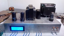

🙂🙁Everything goes well except the hum...Listening and music🙂
probe X10
1khz-50khz
probe X10
1khz-50khz
Attachments

Last edited:
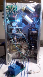
Many signal runs, transformer and chokes in proximity, some ground loop in the wiring you have to spot and solve?
- Home
- Amplifiers
- Tubes / Valves
- 6V6 line preamp