Idid my own boards and used cut down heatsink USA profile, 6" wide. It had both channels main heat producers on it. Got too hot.
The outboard one. Its easy, listen: IRF840 has 1.0C/W thermal resistance core to case. If you have 45C in a box like with this preamp with all the radiators from heaters PSUs, tubes near, regs sinks contributing, load resistors hot etc. and using say a single 1C/W sink for two regs, it will go up 18.2C (14W*1.3C/W) from ambient because I derate the sink by 30% due to hot spot mounted semis uneven surface heat spreading. And that is when fins are perpendicular to air flow by natural convection. 45+18.2C=63.2C on sink's fins to touch. Now a normal Silpad can give additional 1.2C/W. 7W on each IRF840 times 1.2=8.2. Add it to 63.2=71.6C on each 840's body (case). Its hot nucleus gets 1C per W more thermal resistance trying to dissipate to its case's body, thus reaches 71.6+7=78.6C. Those silicone chips inside 840s are 125C rated before meltdown. Using the above points discussed, you may project the spec of any common sink or individual ones flanking the box for two regs, factor in box ambient correctly, how much spare current ups how much temp, everything. In any case isolate well. The Mosfet tab carries B+. !!!!
P.S. Consider that electronics live 4 times longer each time we halve their operating temperature. Use a contact K-Type thermocouple to have a temp picture of everything I mentioned. Flukes have that brown one, some others have the yellow end one, and there are cheap IR thermometer guns but good only for black surfaces and it takes some confirmation of the IR cone aim and distance to get the knack using them to report truly. If you have a cheap DMM get an Amprobe AM-270 since you are in US where you can get it easily, has proper input protection and all the modes, honors its CAT rating, $90. Be careful with cheap or simply unsafe DMMs when messing with HV especially if to measure inline current. That is why I put TP ItoV reading on the SSHV2 board, to save incidents. Best of luck for finishing it in one go, and be careful.
Hi all,
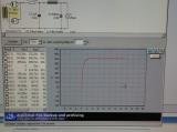
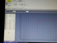
I wish everyone a Good day. My name is zach, I am new to the forum and this is my first post. I am new to diy and electronics but have built a couple tube amps from kits before and now I feel confident enough to build salas 6v6 from scratch. I have most parts to complete the preamp and have procured the power supply components to be used. I'd like to make a separate supply for each channel hence i bought 2 power transformer and 2 supply chokes. As i feel the preamp is worth the effort and cost. I modeled the power supply at PSUD designer but do not know how to attach the simulation results. this is what i did.
this is only for 1 channel!
power transformer is a hammond 272fx- 600vct@ 173ma with sec. dcr of 143ohm and hammond 193j- 10H@200ma with dcr 82 ohm. rectifier will be type 83MV.
thank you!
Attachments
hi!
what is the total current draw of the circuit including 2 salas regulator? thanks
I believe it is about 44ma for both channel! i haven't built the salas high voltage regulator yet, but i don't think it needs to be accounted for when summing up the the current draw of the circuit. Im basing this only from my limited understanding( I really don't know anything) and I might be wrong., So we need the inputs of those who know.
each SSHV2 needs 20mA to operate properly ...
you must add it up ....
thanks for clarifying! Can I operate the sshv regulator at around 50ma to have some extra legroom? if so the total current draw for one channel will be 70ma, that is 50ma for the high voltage regulator and 20ma for one channel. Did i understand this correctly?
thank you
yes thats correct, though I dont know if there is any benefit of operating the regulator at 50mA , manual says 20mA is enough ...
you can find it here (first post by Teabag)
http://www.diyaudio.com/forums/group-buys/206033-gb-salas-sshv2-regulator.html
you can find it here (first post by Teabag)
http://www.diyaudio.com/forums/group-buys/206033-gb-salas-sshv2-regulator.html

Better not have the laminations of that big power transformer face the 6V6, it is a Beam Power Tube...
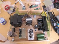
little progress so far,
done some woodworking, finished the SSHV2 and one filament supply ...
I think theres not enough space, which layout seems better ? other options ?
It seems you are a perfectionist.... following your work with the utmost interest.
- Home
- Amplifiers
- Tubes / Valves
- 6V6 line preamp