Will 2 6ax4 damper diodes in full wave mode be good? ive read that they need a lot of current load for them to sing. I have about 16 of them, and thinking of using them. I'll see what I can do with psud as soon as I get home.
That would give you sufficient voltage for regulating at about 340V with 47R R1, but 5R4GY is a more open sounding tube in my opinion. But its more limpid for voltage loss. So 300V and 7.5K load does not make it worse and you can use 5R4GY.
Thanks salas
Will 2 6ax4 damper diodes in full wave mode be good? ive read that they need a lot of current load for them to sing. I have about 16 of them, and thinking of using them. I'll see what I can do with psud as soon as I get home.
Never used such but I have read they are good. Others may have practical experience to inform you more if they read.
dampers can be had at a dollar each....they have indirect heated cathodes and therefore lower forward voltage drops even at current levels seen with the traditional tube rects....
Ill try using 6ax4 instead. Hope theyll sound good. By the way if ] just use ac on the 6v6 heaters are they going to cause hum?
Thanks salas
Another thing, you wrote you already got Hammond 193J choke, yes? Make R1 in the PSUD picture 150R for the 272HX Tx and 5R4GY with that choke. It had a 5H example.
Ill try using 6ax4 instead. Hope theyll sound good. By the way if ] just use ac on the 6v6 heaters are they going to cause hum?
i do not think so, look at the heater cathode voltage ratng, they should be about 300volt or so...http://tubedata.milbert.com/sheets/093/6/6AX4GTB.pdf
do not put too much faith on "rectifier tubes singing", their mission in the amp is to convert ac to dc and not have too much forward drop....
Thanks, ill do that.Another thing, you wrote you already got Hammond 193J choke, yes? Make R1 in the PSUD picture 150R for the 272HX Tx and 5R4GY with that choke. It had a 5H example.
Ill try using 6ax4 instead. Hope theyll sound good. By the way if ] just use ac on the 6v6 heaters are they going to cause hum?
What voltage those gonna give for that Hammond TX or what else you may take care about them ask Tony, for 6V6 in the line amp and AC I can tell you it can be made hum-less with careful construction. Especially for the proximity of heater cabling and signal cabling.
i do not think so, look at the heater cathode voltage ratng, they should be about 300volt or so...http://tubedata.milbert.com/sheets/093/6/6AX4GTB.pdf
do not put too much faith on "rectifier tubes singing", their mission in the amp is to convert ac to dc and not have too much forward drop....
Hi tony,
Thanks for the input. Yea I got the 6ax4s for less than a dollar a pop. Actually I got them at a garage sale along with a single altec 605a for $10 bucks.
AC voltage on the heaters for the 6v6 was inho the way to go. I tried various DC set-ups including a SSLVR and all of them sounded dead to me. So I am back to a simple tranny and a resistor to keep the voltage down to 6.1V. It is a matter of opinion though.
No Hum.
No Hum.
Could you show a schematic. This is basically tying ground of the heater to a higher voltage tapped off mains supply? Are you using SSHV2, SGrergory?
Yes I use the SSHV2.
FYI, I also use a ccs as the load. I built the Bootstrap CF.
To lift the heater it is a simple, a relativly high impedance voltage divider. If you know your B+ voltage then calculate the value of the divider to get the proper voltage. You will also need to bypass the lower resistor to ground with caps. I used a 1uF poly and a 47uF electrolytic 50V I had out of my parts box. I will see if I can draw a quick schematic later and post if someone doesn't have it handy. Pretty common approach
Voltage divider for lifting heaters
Here is what I use for lifting heaters. Lots of opinion and theories as to what voltage to lift heater to. I try to keep it simple.
For me: Rule number one. Make sure that the heater to cathode voltage is within spec. Then, if feasible, select a voltage to get the heater above the operating cathode voltage slightly.
Attachments
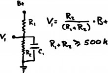
Yes. V1 is the "new ground" for the heater circuit. I just tie one leg of the heater trany out to it. In my case I rarely use the PT heater windings and opt for a seperate heater tranny. But this works in any case.
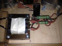
Attached photo is of complete heater supply including voltage drop resistors for 6.1V and Voltage divider for lift. You can see the caps and smaller resistors buried underneath Vdrop resistors
Attached photo is of complete heater supply including voltage drop resistors for 6.1V and Voltage divider for lift. You can see the caps and smaller resistors buried underneath Vdrop resistors
Attachments
Last edited:
- Home
- Amplifiers
- Tubes / Valves
- 6V6 line preamp