I wouldn't get too hung up on PSRR in a guitar amp, and there's nothing wrong witht he self bias version you have- many people use that. You haven't said how your power supply is arranged. Maybe a bit more filtering is all that's needed? Are you sure it's not heater hum you're picking up?
Thanks again for reply Merlinb.
My supply is xformer-ez80-8H-100uf-50uf-30uf, i know i should put a few uF's before the choke but my case restricted me.
That should be ok shouldnt it?
Im pretty sure its not heater hum, ive done the usual AC heater layout and twisting tricks. The waveform is definatly an exact match to the ripple on the supply.
I am running an 0a2 regulator as spare in my supply, ill try and get it regulating for my first stage.
Regards
Craig
I have never used a regulator in an an amp, but I hear they can be noisy?
You didn't mention if your heater supply is elevated or centre tapped? Either one is essential for noise reduction. Simply connect the heater centre tap to a reference of about 40V from a potential divider from HT. (If the tranny has no heater centre tap, create one using a pair of 220R resistors, you may already be aware of this- you seem to know what you're doing).
The next useful trick is to reduce the size of your coupling cap from the cascode to the next stage. If you set its low roll-off to about 100Hz, you'll immediatly get -3dB HT noise, and -6dB heater hum (I think thats right!)
Don't worry about losing bass response, low notes on the guitar only go down to about 130Hz, and there is plenty of scope to regain bass in later stages in the amp. Altogether it will tighten up the bass and reduce 'woofiness'.
Oh, and have you considered replacing the EZ80 with silicon diodes to raise the HT?
I also see you're using a choke input filter. These are ok if you did all the maths, but unless you draw the right amount of current (and without the power stage you're drawing very little) they don't work. Try cutting the choke out of the circuit and hook in a 1k power resistor instead and see if it makes a difference, or add a cap right after the rectifier.
Also consider that your power transformer placement can be a source of hum in the cascode.
I am not floating my heaters at the moment, i will do the modification you suggested thanks.
I have connected my first stage to a regulator tube now and the ripple is now 100mV,
( i think im going to have to make my voltage dropping resistor for the 0A2 very small to get enough current when my 6v6 is connected. I may not even have enough voltage to run the 0A2!).
I did consider using diodes at the beginning, but one of the aims of this project was to use up all my spare tube bits, Although i may be forced into using them if my regulator drops out.
Thats a good idea! literally filtering the hum out haha, i guess you can only get away with this on guitar amps.
My power supply is in a seperate case to my amp so i shouldnt get any problems from transformer induced hum.
I intend to connect the power stage as soon as ive figured out how to wire my o/p transformer so ill leave the choke in cicuit (its nice and neat, quite rare for me).
Regards
Craig
PSU
Attachments
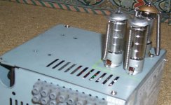
Thanks, the old PC PSU made quite a good valve PSU case all in all.
I have managed to obtain another transformer for this amp, its rated at 250-0-250 @ 50mA. I hooked it up and it works fine under load giving me 250VDC on my circuit 😀.
A few tweaks to resistor values and ill be away.
One thing i am unsure of is a cathode bypass capacitor for the 6V6 bias resistor. I have seen values of 100uF, should i add one to my circuit?
edit: Just re-read Tubelabs post, i guess i should add one.
Thanks
Craig
I have finished the amp today (ive been slow, ironing out noise issues etc).
It has a gain of about 385 and works fine with a signal generator driving it.
Although when i connect my guitar to it i cant hear a thing, i put a distortion pedal in between at max volume and i do get sound but its not very loud.
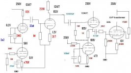
I think the input cascode is improperly biased, the cathode voltage of the first tube looks far too low?
I dont really know how to start calculating values for this stage
The rest seems alright to me, 5mA in the tube buffer stage.. is this enough to get the most out of my 6V6?
Thanks
Craig
It has a gain of about 385 and works fine with a signal generator driving it.
Although when i connect my guitar to it i cant hear a thing, i put a distortion pedal in between at max volume and i do get sound but its not very loud.
I think the input cascode is improperly biased, the cathode voltage of the first tube looks far too low?
I dont really know how to start calculating values for this stage
The rest seems alright to me, 5mA in the tube buffer stage.. is this enough to get the most out of my 6V6?
Thanks
Craig
Attachments
Any ideas guys?
Do you think the cascode needs biasing better, if so how do i go about doing it. Do i use only 1/3HT voltage on the plate of the lower tube to get current and bias? how do i get the anode load resistor value?
Craig
Do you think the cascode needs biasing better, if so how do i go about doing it. Do i use only 1/3HT voltage on the plate of the lower tube to get current and bias? how do i get the anode load resistor value?
Craig
Craig405 said:Any ideas guys?
Do you think the cascode needs biasing better, if so how do i go about doing it. Do i use only 1/3HT voltage on the plate of the lower tube to get current and bias? how do i get the anode load resistor value?
Craig
If the circuit diagram in the other post is accurate, it's no wonder you don't hear anything. With 0.2Vdc on the grid, and 56Vdc on the cathode, the upper half of your "cascode" is way into cutoff. Also, I wouldn't use a 12AX7A as a cascode anyway, as this type has a very low g(m).
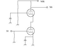
The cascode requires a voltage divider to set the voltage at the grid of the upper triode, which, in turn, sets the voltage at the bottom triode, less the required bias voltage, of course. The control grid of the upper triode also needs a good bypass to AC ground since this is a grounded grid configuration and will oscillate nastily if there is too much impedance between the grid and AC ground.
I, personally, wouldn't build a cascode from a 12AX7A. I'd use something like a 6BQ7 which was designed for this very purpose. It has a much higher g(m) that doesn't collapse so quickly with reduced plate current. Although it does like a rather higher than normal Vpk for good linearity.
I have a "white paper" on designing these on my HD that I could e-mail you (can't find a link -- maybe it doesn't exist anymore?)
Attachments
Thanks very much!
Id be very interested to see that white paper.. Ill drop you an email containing my email address.
Since making my last post on this thread i scrapped the cascode and replaced it with // anode follower 12AX7's just to get it working.
Well.. still doesnt work lol, im about to plough right into it tonight to find the problem.
Regards
Craig
- Status
- Not open for further replies.
- Home
- Live Sound
- Instruments and Amps
- 6V6 guitar amp design attempt