soulmerchant,
Caution:
If you put a bias battery from ground to the cathode . . .
You Will be charging the bias battery whenever the amplifier is on.
1. Many batteries are not supposed to have charging current applied (Alkaline, Carbon Zinc, Lithium non-rechargeable, etc.)
2. Rechargeable batteries normally have a maximum voltage rating. At that maximum voltage, the charger circuit is supposed to turn off.
But the cathode is still going to be passing current, and charging the battery.
What will happen when the battery is fully charged, and the cathode is still passing current into the battery (Overcharging)?
3. Some experimenters used NiCad rechargeable for cathode bias.
I never liked NiCads for anything, they tend to be wimpy.
Why do you think the battery industry kept designing, and came out with Dry Lead Acid Gel cells, Nickel Metal Hydride, Lithium Ion rechargeable, etc.
Your Mileage May Vary

@soulmerchant Thanks, these are very good points indeed. I am using Mills allegedly non-inductive wirewound resistors, but I can definitely consider film. Capacitors are standard F&T electrolytics, will try a bigger value as well.
@rockies914 I honestly hope this is overkill and it would simply work as drawn. Just got worried when I was told that 6SN7 is a poor choice for interstage driving tube (due to high Rp I suppose) and capacitor might cause issues with transformer inductance.
@rockies914 I honestly hope this is overkill and it would simply work as drawn. Just got worried when I was told that 6SN7 is a poor choice for interstage driving tube (due to high Rp I suppose) and capacitor might cause issues with transformer inductance.
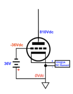
Hi everyone - I have been thinking about using 36V battery (4 x 9V in series) for fixed bias duties. Not sure if this will work well, but according to tubecad journal it is possible. In my case, this is for an upcoming 814 output tube. See attached. Any issues? I am under the impression that the fixed bias requires a small amount of current (~10 to 30ma). If so, the 4 x 9V 1.2Ah batteries would trickle recharge, correct?
Attachments
banpuku,
There are lots of threads about battery bias.
Are you going to use the 814 in single ended class A1 mode?
The answer to that is real important for battery bias.
The 814 is designed for Class C operation, With high negative bias, and very large signal to the grid, and then it draws lots of grid current.
Class C is Not for Audio (well, perhaps it works for a real funky sounding Guitar Amplifier).
The filament alone, dissipates 32.5 Watts into that beautiful glass envelope!
I hope the 814 grid in Class A1 has less than a few uA of quiescent grid current.
Your schematic is not representative of a practical and real battery bias circuit, no way to apply signal.
Look at my Post # 6 for details of how to connect the battery, to bias a Class A1 amplifier.
I successfully used series connected 9V alkaline batteries to bias 45, 2A3, and 300B tubes (the number of 9V in series, according to the tube bias voltage requirements).
They operated for at least 2 years that way.
Please let us know more about your 814 plan details.
banpuku,
Caution:
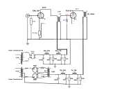
Your 36V battery is shorted out by the interstage transformer secondary.
9V alkaline batteries in series will smoke the secondary.
Ouch!
Instead, connect the 36V, just as I said in post # 6.
Connect from the Top wire of the Interstage secondary, to the + end of the '36V battery';
Connect from the - end of the '36V battery', to the control grid of the 814.
Done.
Or, Better yet . . .
To remove the effect of any capacitance from the '36V battery" to ground, then break the connection of the Bottom wire of the Interstage transformer to ground, and insert the '36V battery' between ground (+ battery), and the bottom of the Interstage secondary (- battery).
There, that is all.
Caution:
Your 36V battery is shorted out by the interstage transformer secondary.
9V alkaline batteries in series will smoke the secondary.
Ouch!
Instead, connect the 36V, just as I said in post # 6.
Connect from the Top wire of the Interstage secondary, to the + end of the '36V battery';
Connect from the - end of the '36V battery', to the control grid of the 814.
Done.
Or, Better yet . . .
To remove the effect of any capacitance from the '36V battery" to ground, then break the connection of the Bottom wire of the Interstage transformer to ground, and insert the '36V battery' between ground (+ battery), and the bottom of the Interstage secondary (- battery).
There, that is all.
Last edited:
OK - so LED bias looks cool. I get it. But when bypassed with a large cap, it really does not matter if you use a LED, a series of diodes, or a resistor.
Which brings us back to the resistor. Why use it? - Because as the tube ages, the bias will self-adjust. Not so when using diodes. And, when not using a byppass cap on the cathode, the cathode resistor provides local feedback. Some likes the sound of a de-generated triode as it normalizes the amplification and helps when the tube is over-driven by a large input signal. So yet again: we have many options in DIY audio. So let your ears be your guide. 😉
Which brings us back to the resistor. Why use it? - Because as the tube ages, the bias will self-adjust. Not so when using diodes. And, when not using a byppass cap on the cathode, the cathode resistor provides local feedback. Some likes the sound of a de-generated triode as it normalizes the amplification and helps when the tube is over-driven by a large input signal. So yet again: we have many options in DIY audio. So let your ears be your guide. 😉
banpuku,
The bias voltage from the 36V battery does not have any significant quiescent current to the 814 tube.
But suppose the 814 had 10uA quiescent grid current.
And suppose the interstage output transformer secondary has a DCR of 1000 Ohms.
(10 x 10^-6 Amp) x (1 x 10^3 Ohm) = 10 x 10^-3 Volts (10 mV drop).
36V - 10 mV is pretty close to 36V.
Just insert your grid quiescent current, and your interstage transformer DCR, and multiply to find the voltage drop.
For posterity, these are two nice articles about placement of battery for battery bias. Interestingly, they reach different conclusions but it's quite insightful to read about the reasoning.
1. https://www.tubecad.com/2014/11/blog0313.htm
2. https://www.audio-talk.co.uk/fiultra/KISS 126 by Andre Jute.htm
1. https://www.tubecad.com/2014/11/blog0313.htm
2. https://www.audio-talk.co.uk/fiultra/KISS 126 by Andre Jute.htm
I would not use battery bias, 10 years later... You can build a small negative power supply with a small regulator and grid bias your input tube, add input capacitor.
LEDs as cathode bias have a very small but very non-linear impedance. It's a small impedance, so may not be significant in the relevant sum of its impedance plus reciprocal of the valve's transconductance (and its distortion contribution is weighted in the same proportion), but it's too small to practically bypass with a capacitor, maybe a few ohms.But when bypassed with a large cap, it really does not matter if you use a LED, a series of diodes, or a resistor.
All good fortune,
Chris
- Home
- Amplifiers
- Tubes / Valves
- 6SN7 with fixed bias