Hello,
I am building an amp with 6SN7 driving interstage transformer as per schematic. I was told that it’s a bad idea to use cathode bypass capacitor on 6SN7 with an IT due to possible resonance. Removing capacitor is not really an option due to resulting impedance.

Would a fixed bias be a better option? For example a 6V battery instead of resistor and capacitor, would that work?
Thanks.
I am building an amp with 6SN7 driving interstage transformer as per schematic. I was told that it’s a bad idea to use cathode bypass capacitor on 6SN7 with an IT due to possible resonance. Removing capacitor is not really an option due to resulting impedance.
Would a fixed bias be a better option? For example a 6V battery instead of resistor and capacitor, would that work?
Thanks.
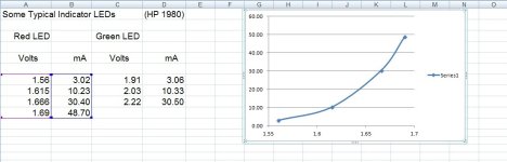
You could replace the cathode resistor and capacitor with 3 green (~2V each) LEDs to get the 6V bias.

The 10mA cathode current (which equals plate current) would constantly charge that battery ... not good for a primary battery, but you could charge your rechargeable flashlight battery this way ;-)For example a 6V battery instead of resistor and capacitor, would that work ?
Instead you can feed -6V from a battery or other power supply via that 1M resistor to the grid and ground the cathode. No current draw, battery will last. However that requires a coupling cap at the input ...
If you want to use a 6V battery for bias . . .
Connect the 6V battery positive end to the junction of the 1 Meg resistor and RCA input jack.
Then connect the 6V battery negative end to the 220 Ohm grid stopper (the end of the 220 Ohm resistor that used to connect to the junction of the RCA input jack and 1 Meg resistor).
The series circuit of the signal path will now be . . .
RCA jack center pin, battery positive end, battery negative end, 220 Ohm grid stopper, grid of the 6SN7.
There is no current in the battery, unless you apply way too much signal to the RCA jack center pin, and that will draw grid current on the 6SN7 (which attempts to charge the battery; it does not discharge the battery).
By the way, turn down the signal volume to the RCA jack if you are drawing 6SN7 grid current, because that sounds distorted on a Class A1 stage.
With battery bias, you may have to adjust the B+ voltage to the 6SN7 interstage primary (the resistance of the 6.8k resistor).
Last edited:
Thanks everyone for the suggestions!
Just to clarify on the battery position - if I put it in series with grid stopper, then I don't need the coupling cap on input, is that correct understanding?
Just to clarify on the battery position - if I put it in series with grid stopper, then I don't need the coupling cap on input, is that correct understanding?
You can easily check if that really takes place by simple frequency response measurement. I am not at all sure that it is any issue. If it were, then the same problem would appear with cathode biased SE-output stages. You can also try different (up to 1000uF) values of the cathode capacitor.I was told that it’s a bad idea to use cathode bypass capacitor on 6SN7 with an IT due to possible resonance.
Concerning your circuit diagram, I would add a damping resistor of some 20...100k parallel to the IT-secondary to avoid possible resonances.
At present the load of the IT is quite reactive and indefinite.
Last edited:
Hugo145,
The return of the battery positive is to the Rg to ground.
There is no current unless the 6SN7 is gassy, then there will be grid current even if there is no signal.
Always replace gassy 6SN7 tubes.
ColinA123,
I used Nine 9 Volt Alkaline batteries for 300B grid bias, and Five 9V alkaline for 2A3 tube.
I used 3V Lithium, and 6V Alkaline batteries to bias various input tubes and driver tubes.
These all ran for at least 2 years.
Check them every 6 months, just so you can sleep at night.
Years ago, I used fixed adjustable bias.
Then battery bias.
Now I use self bias, and I also use CCS bias for cathode coupled phase inverters.
I do not recommend using battery bias in the cathode circuit, some use NiCad that way, not me.
Just my opinions and experience.
Why would any serious audiophile put a non-linear device such as a SS Diode in the audio path?You could replace the cathode resistor and capacitor with 3 green (~2V each) LEDs to get the 6V bias.
How much gain do you need? Better to use an unbypassed cathode bias resistor. That adjusts for tube aging, 👍
Attachments
Because I'm not a serious audiophile, I'm more interested in schematics, volts, amps and waveforms.
Good to know, so am I. You can see my work all over DIY & going back more than 20 yrsBecause I'm not a serious audiophile, I'm more interested in schematics, volts, amps and waveforms.
in Glass Audio, AudioXpress & Wireless World. 😀
Thanks @artosalo, good point, I will check if this is really a problem in practice. With 106H inductance and 47uF capacity resonance frequency is 2.2Hz, not sure what this actually means in practice.
Thanks @6A3sUMMER, I was thinking the same, battery in series with grid. New lithium thionyl chloride Li-SOCl2 batteries hold their charge for decades and their discharge curve is extremely flat.
Thanks @6A3sUMMER, I was thinking the same, battery in series with grid. New lithium thionyl chloride Li-SOCl2 batteries hold their charge for decades and their discharge curve is extremely flat.
Try more than 47uF cathode bypass. Go for 100uF. Get NEW electrolytics, and don't go for hocus-pocus audiophool caps.
But more importantly, make sure the cathode resistor is non-inductive. It needs to be a film resistor. When I was building super-cheap, I paralleled multiple smaller wattage film resistors. You would be surprised how much difference this can make.
Or play around with LED's. If you are lucky you will find a good batch that don't sound strange. Like ColinA123 said, batteries sound good until you get worried about turning the amp on...
Ian
What is cheaper? lithium thionyl chloride Li-SOCl2 battery or 100uf cap? not sure here.... anyway would be nice to hear if you did the battery in series with grid experiment, and how it worked out.
Ian
Ian
If you use the battery to negative bias the grid, you should not use the cathode resistor+cap network on the cathode. In this case, cathode is grounded, grid has it's negative bias from the battery.
Thanks! I didn't say that right, sorry. I was thinking of having both, meaning a smaller resistor with a cap in parallel, along with a battery (with smaller voltage) to make up for the undervalued resistor 🙂
You can also use a battery (a rechargeable one) to positive bias the cathode (instead of the RC network). I did this before, until I started to get worried and was checking the battery's voltage before turning on the amp.
I think it was mentioned that LED bias works nicely too.
Why do you want to make changes? Are you unhappy with the sound? 6sn7 isn't really up to driving 2a3 in this circuit, but maybe it is ok for your speakers and the room, etc.
I think it was mentioned that LED bias works nicely too.
Why do you want to make changes? Are you unhappy with the sound? 6sn7 isn't really up to driving 2a3 in this circuit, but maybe it is ok for your speakers and the room, etc.
- Home
- Amplifiers
- Tubes / Valves
- 6SN7 with fixed bias