The tube circuit is pretty much the same as my old BH Foreplay using 12AU7's, minus the CCS on the VA.
Mike's power supply is on another level thou.
jeff
Mike's power supply is on another level thou.
jeff
That's a lot of PSU for a mere 150V!

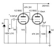
As Jeff says, ir is a DC coupled Common Cathode>Cathode Follower.
Bottlehead used 12AU7, Frank deGrove has an (old thread) on a 6SN7 version, i have a version with 6DJ8/6922/6C23∏ (can use 6N1P but it needs twice the heater current).

And for the 6DJ8

Given it is a linestage i don’t think the PS is all that much overkill… here is the one Frank did.

Do note that adding a CCS to the to of the first stage and the bottom of the second stage makes for significant improvements. Particualrily on the follower.
dave
Bottlehead used 12AU7, Frank deGrove has an (old thread) on a 6SN7 version, i have a version with 6DJ8/6922/6C23∏ (can use 6N1P but it needs twice the heater current).
And for the 6DJ8
Given it is a linestage i don’t think the PS is all that much overkill… here is the one Frank did.
Do note that adding a CCS to the to of the first stage and the bottom of the second stage makes for significant improvements. Particualrily on the follower.
dave
Referring to the schematic of Post # 1:
1. The output voltage of a circuit of 1uF and 470k Ohms will go to 0.37 x 50V = 18.5V in 0.47 second (1 RC time constant).
Better use a Very Slow Start B+, to keep large voltages out of the preamp output (going to the power amplifier).
2. A 6SN7 has 2600 to 3000 uMhos. A 12AU7 has 2200 to 3100 uMhos. The cathode impedance varies from 323 Ohms to 455 Ohms.
Using a 27k Ohm cathode resistor, or using a CCS (constant current sink) in the cathode follower will not significantly change the output impedance of the preamp.
Changing from a 27k Ohm resistor to a CCS:
Using a CCS Will reduce the distortion a little bit if you only load the preamp with a 1 Meg Ohm scope probe.
Using a CCS will Not reduce the distortion significantly if you load the preamp with a 10k Ohm input impedance of some solid state power amplifiers.
Using a CCS in the cathode follower, and a power amplifier with an input impedance of 20k, 47k, 100k . . .
Your Mileage May Vary.
Two 6SN7 tubes (stereo), have 1.2A of filament current.
With 10,000 uF filter capacitor, and 120Hz full wave rectification, the ripple will be 159mV peak to peak (0.159V peak to peak).
And, it will not be very sinusoidal, it will have lots of mid and high frequency harmonics.
Be sure to keep the filament ground loop currents out of the rest of the amplifier circuitry.
Or, just use AC powered filaments and get real good 6SN7 tubes,
Or use a very clean DC supply.
Last edited:
he is on youtube in his 5670 preamp video he stated an output capacitor was needed to keep dc out of the output transformer ,even though i am no expert than seemed strange ,i looking at the vtv octal preamp now to go with the je labs simple 45/2a3 using a 2a3
The original Foreplay design was by George Wright, some time before the 1998 release. There were a lot of variations, both official and by owner/experimenters, before it was discontinued. The circuit in Post #1 incorporates many of them. I'm pretty sure the basic topology goes much further back!The tube circuit is pretty much the same as my old BH Foreplay using 12AU7's, minus the CCS on the VA.
...
@planet10 , @everybody - could you please help me to understand what is the idea behind this resistors network? It obviously create local negative feedback introducing part of output (voltage divider 820R/10k) via 220k back to grid. BUT WHY??? I see no reason of doing so. This circuit has by itself low output impedance, broad bandwidth and great linearty. Why to create local feedback loop?? By a way - have anybody noticed that circuit next below it (without feedback and coupling cap) is identical what Audio Note use in M7 🙂?
Attachments

This is polarization method for cathode follower, not a negative feedback loop.
You need grid at lower potential than cathode is.
You need grid at lower potential than cathode is.
Because cathode followers grid is directly polarized from the first stage anode without capacitor, which is blocking DC polarization in your example two posts above.Understand, thank you. In that case: why in 2nd circuit shown at the same diagram we don't do so?
I think Triodos means 'bias' when he writes 'polarization' in his posts above. The bias of the grid needs to be negative relative to the cathode.
Exactly 🙂I think Triodos means 'bias' when he writes 'polarization' in his posts above. The bias of the grid needs to be negative relative to the cathode.
- Home
- Amplifiers
- Tubes / Valves
- 6SN7 preamp circuit opinions