I have a boat load of different 6SN7's I would love to make a preamp with. I don't want to make an Aikido design, I am thinking just a simple common cathode gain stage feeding a cathode follower, one bottle per channel. My problem is I don't want too much gain. Do I use a little feedback to get the gain down? Or do I just split the anode resistor load into two resistors and take the output from the junction? I open for any other suggestions as well.
I need two outputs, one for my main stereo and the other for a subwoofer. I may want to incorporate a low pass filter into the sub out, any ideas? I am not opposed to using an opamp for the sub out and go with an active filter.
The power supply is probably the most important thing so I am going with a Maida HV regulator, ~300v.
While somewhat of a fashion statement/trendy an SRPP realized with the 6SN7 is a pretty decent performer IMLE. The downside is supply voltages of 300V - 350V are needed for decent performance. (1K cathode resistors and about 8mA of current, simple as dirt.)
An op-amp is not a bad idea for the output to the subwoofer.
An op-amp is not a bad idea for the output to the subwoofer.
Taking the excess gain (along with extra distortion) and then throwing it away might be the least attractive option. You could reduce B+ and reduce the anode load resistor instead, but you don't want reduced B+ for the cathode follower. I would split the anode load and bootstrap it from the CF, and then add series input and feedback resistors to set the desired gain. Make an augmented anode follower, in other words.
I like the humble MU-follower for 6SN7. Couple it with a MOSFET source follower to drive pretty much any cable.
since you're looking for different outputs, you might want to do two different EQ's between MU-Follower and Source follower. MOSFETS are not necessarily expensive - you could use two per channel. One with EQ for subwoofer and one without.
Ian
since you're looking for different outputs, you might want to do two different EQ's between MU-Follower and Source follower. MOSFETS are not necessarily expensive - you could use two per channel. One with EQ for subwoofer and one without.
Ian
How much voltage gain is too much?
And how much voltage swing do you need at the output?
Without numbers, the design does not have a target; you can not hit a target that does not exist.
A 6SN7 common cathode stage followed by a 6SN7 cathode follower can have a gain of less than 17. It can be a very simple circuit, just Rs and Cs, and have very low distortion too.

The obvious options are either to use shunt feedback from the CF back to the input grid, which is simple but means lower input impedance and worse noise, or to build a ring-of-two (series feedback).My problem is I don't want too much gain. Do I use a little feedback to get the gain down?
You could also build a common-cathode amp, but the output impedance will be rather high unless you also add a cathode follower (cathode repeater).
Attachments
Last edited:
All great advice!
As far as gain goes I don't want more that 10, preferably less.
I have much to think about Now so thanks guys, my mind keeps thinking cathode repeater. I will pull out the data sheets later.....crunch some numbers and run some simulations.
As far as gain goes I don't want more that 10, preferably less.
I have much to think about Now so thanks guys, my mind keeps thinking cathode repeater. I will pull out the data sheets later.....crunch some numbers and run some simulations.
Taking the excess gain (along with extra distortion) and then throwing it away might be the least attractive option. You could reduce B+ and reduce the anode load resistor instead, but you don't want reduced B+ for the cathode follower. I would split the anode load and bootstrap it from the CF, and then add series input and feedback resistors to set the desired gain. Make an augmented anode follower, in other words.
Perhaps if going with reduced B+ to limit gain, use an active load in the cathode of the cathode follower? That way the cathode follower could see a large value load there, but without the voltage drop necessary for a cathode load resistor.
--
As far as gain goes I don't want more that 10, preferably less.
How about using the 6AH4 for the gain (~8) stage, and keep your 6SN7 for the CF.
jeff
The 6AH4 is a 7.5W power tube. It is probably only linear when it is standing quite a bit of plate current. That could be a good thing in this case.
If you use it that way, the tube plate resistance is low, about 1800 Ohms.
Just use a cap from the plate to a resistor to ground to drive a 3 foot low capacitance shielded cable going to the main power amp (no cathode follower is required).
That same cap from the plate can also drive a parallel RC low pass network to drive the subwoofer amp.
A one stage preamp.
A CCS plate load will reduce the required B+ voltage, and a choke loaded plate will do the same. Or, just use lots of B+, and a resistor plate load.
Try simulate this.Gain between 9x to less then 1x 🙂All great advice!
As far as gain goes I don't want more that 10, preferably less.
I have much to think about Now so thanks guys, my mind keeps thinking cathode repeater. I will pull out the data sheets later.....crunch some numbers and run some simulations.
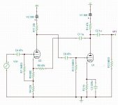
It has positive feedback to get the open loop gain up.And the negative feedback set the gain.
Mona
Attachments
How about using the 6AH4 for the gain (~8) stage, and keep your 6SN7 for the CF.
You could also use a 12B4A the same way, and not need the cathode follower. Almost as low output Z (not that that's necessary in most cases).
http://www.diyaudio.com/forums/tubes-valves/137771-12b4-preamp.html
http://www.diyaudio.com/forums/tubes-valves/258974-6ah4-preamp-great-option-line-stage.html
http://www.diyaudio.com/forums/tubes-valves/102352-6v6-line-preamp.html
But I thought the original question was about how to use 6SN7 for a line amp without too much gain...
Last edited:
Try simulate this.Gain between 9x to less then 1x 🙂
It has positive feedback to get the open loop gain up.And the negative feedback set the gain.
Mona
Where would you put the volume control?
I admit, I, and others got away from the original question which was to use 6SN7s.
They are linear; and the idea was to use the ones that were already on hand.
You could use a split (2 series resistor) plate load, but then the B+ would need to be much better filtered. A gain of 17 could easily be made to be 8.5 with 2 equal series resistors as the plate load.
7,700 Ohms plate resistance and a 25k load has just a very little power supply rejection.
7,700 Ohms rp driving 2 each 12.5k resistors, with the output taken across the junction of the split resistors has almost no power supply rejection.
You could cap couple to the 2nd section of the 6SN7 as a cathode follower. Or you could DC couple, but most certainly have to elevate the filament because of the higher DC voltage at the junction of the two 12.5k resistors.
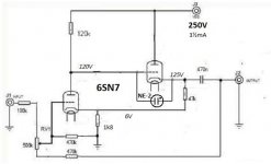
Didn't now he need one 😕Where would you put the volume control?
But if you insist 🙂
Mona
Attachments
Now that this discussion has gone the route of lower gain, I am surprised nobody has suggested a step-down transformer yet.
Ian
Ian
Now that this discussion has gone the route of lower gain, I am surprised nobody has suggested a step-down transformer yet.
Well I was going to, but I'm glad you brought it up.🙂
jeff
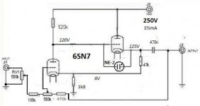
Here's the augmented anode follower (shunt feedback) concept I was blathering about earlier, fleshed out for gain of roughly 6 and including the neon safety device. R6 may need a little adjustment to achieve something near 150V at U1A anode. Performance might improve slightly if R6 is bypassed, but bootstrapping will make that a small effect if it exists at all. Output impedance should be well under 600R.

- Status
- Not open for further replies.
- Home
- Amplifiers
- Tubes / Valves
- 6SN7 preamp advice