A recent disaster: https://www.diyaudio.com/community/threads/ai-designed-phono-pre-amp.425386/I wonder if there is an AI algorithm capable of designing a tube amp yet?
I'm not too concerned about our coming robot overlords based on their demonstrated incompetence, but our current overlords aren't much better. Concerning long loop feedback including an output transformer (OPT), there is a useful and easily accessable model for thinking about and understanding the issues involved. It's a stick figure model of two panels, both with the same X of log frequency. One panel has log amplitude as Y, the other linear phase as Y, and it's called a Bode (pronounced as BoDuh) diagram, and is where poles and zeros come from. Very intuitive and understandable and highly recommended - excellent return on a small time investment.
OPTs are so variable, and also almost never specified in any useful way, that Rules of Thumb, normally very useful in vacuum valve tech, have a poorer chance of being right enough for this gig. Maybe, and better than nothing. IIRC you don't have an arsenal of test equipment available, so it's worth a flyer.
All good fortune,
Chris
That's funny. As someone who works around AI and has for a while, I can tell you that there is nothing "intelligent" about it. It's nothing but an algorithm operating on large data sets, even if it can adjust its parameters over time and work quickly. What's funny is that a lot of the data sets used come from scouring the Internet, and we ALL KNOW that if we read information online it MUST be true, right!
Bode diagram
I haven't thought about one of those in years.
OPTs are so variable, and also almost never specified in any useful way, that Rules of Thumb, normally very useful in vacuum valve tech, have a poorer chance of being right enough for this gig.
Probably why I can't find any. I'll stick with the ones shown on the original schematic to see what happens. In a point-to-point amp it's very easy to change the values for testing.
... so it's worth a flyer.
Not familiar with that expression.
IIRC you don't have an arsenal of test equipment available.
Not unless I make some new friends who have test equipment. 😀
If this experiment doesn't work well, there are several schematics posted online for rebuilt versions that people say do work. Even the original schematic with the paralleled triode drivers is reported to work ok with some minor modifications. I can always gut it later and use a proven schematic, but that would not be as fun as fiddling with this design to see what happens.
Sorry, maybe I heard it on some British sourced TV and just adopted it. Or maybe it was from My Fair Lady. Anyway, I just meant might be worth taking a gamble. Also, not yet mentioned, you really want to include a Zobel network across the OPT secondary, especially important for stability, and at low cost and no performance penalty. Try 10R in series with 0u1F or whatever close on hand.Not familiar with that expression.
I don't want to either under- or over- emphasize the importance of having a good mental model of something as abstract as feedback, but without some model we wander. People much smarter than me tell me that the Bode models are a simplification from more complete Nyquist (?) models, and I'm sure there are others, but they work for my pea-brain and I recommend their (short and digestable) study to everyone.I haven't thought about one of those in years.
All good fortune,
Chris
Does anyone here ever find himself asking, "If this is such a great idea, why can't I find other examples of people doing it?
It has often been said that everything that could be done with tube amplifiers has been done, and was done a long time ago.
I can't find an example of anyone using 1/2 6SL7 to drive an EL34 SEP. When you search online for SEP, 98% of what you find isn't SEP because apparently many people don't even know what it is. People apparently think ultralinear and triode are the same as SEP so long as they use EL34. So that makes finding examples more difficult.
Triode - The Jute SEntry used 1/2 6SN7 to drive a SET EL34 with no NFB.
https://www.audio-talk.co.uk/fiultra/Jute-EL34-SEntry.jpg
Triode - The 6SN7 also has been used in SRPP configuration to drive a SET EL34 with NFB, and apparently it also "worked" in pentode but no changes to the NFB values were provided. Seems like a switch to go from triode to pentode also ought to change the NFB values significantly. 😕
https://www.diyaudio.com/community/threads/el34-se-amp-schematic.154796/#post-2463355
Pentode - There is an old Chinese schematic showing 6SL7 in SRPP driving EL34 in pentode with NFB.
https://audiokarma.org/forums/index...-amp-kit-poor-schematic.1072789/post-17470742
The thread is very hard to figure out, but it seems that when he fixed this error he finally got it to "work":
I'm actually considering trying this last example as it seems to be the original intent of this design before it was copied and changed again, and again, and again, and again by various Chinese manufacturers and they seem to think 6SL7 and 6SN7 are interchangeable. 😕 🙄😵 Someone along the way seems to have gotten the idea of simply wiring the driver triodes in parallel like in the Angela guitar amplifier for simplicity: https://web.archive.org/web/2010012...com/stereosingle-endedel34hi-fiamplifier.aspx.
This version does require two driver tubes instead of one. I could easily add my regulated screen supply and also get rid of that rectifier tube using my power supply PCB. I would feed the 6SL7 driver heater with its own AC winding for simplicity. This is the original circuit. I will redraw it with a SS power supply and regulated screens using my power supply PCB. Chinese 6N9P = 6SL7.

It has often been said that everything that could be done with tube amplifiers has been done, and was done a long time ago.
I can't find an example of anyone using 1/2 6SL7 to drive an EL34 SEP. When you search online for SEP, 98% of what you find isn't SEP because apparently many people don't even know what it is. People apparently think ultralinear and triode are the same as SEP so long as they use EL34. So that makes finding examples more difficult.
Triode - The Jute SEntry used 1/2 6SN7 to drive a SET EL34 with no NFB.
https://www.audio-talk.co.uk/fiultra/Jute-EL34-SEntry.jpg
Triode - The 6SN7 also has been used in SRPP configuration to drive a SET EL34 with NFB, and apparently it also "worked" in pentode but no changes to the NFB values were provided. Seems like a switch to go from triode to pentode also ought to change the NFB values significantly. 😕
https://www.diyaudio.com/community/threads/el34-se-amp-schematic.154796/#post-2463355
Pentode - There is an old Chinese schematic showing 6SL7 in SRPP driving EL34 in pentode with NFB.
https://audiokarma.org/forums/index...-amp-kit-poor-schematic.1072789/post-17470742
The thread is very hard to figure out, but it seems that when he fixed this error he finally got it to "work":
well all, thanks for all your advice on the muddy sound deep booming bass with that SRPP circuit. i think i went down a rabbit hole, trying coupling caps and NFB resistor value, PTO wiper cap to the 6sl7 grid. BUT i overlooked ONE THING! i forgot to ground to chassis the common to speakers output transformer, that changed every thing 🙂. however, now i don't have much Bass, and a bit crisp on top.
No ground connection means no negative feedback. High output impedance makes for muddy bass, so all of that tracks. Less feedback = higher output impedance.
got the amp working as good as i know how, happy. i did app [sic: apply? add?] the feedback resistor from 8 ohm tap on OPT using 27k.
I'm actually considering trying this last example as it seems to be the original intent of this design before it was copied and changed again, and again, and again, and again by various Chinese manufacturers and they seem to think 6SL7 and 6SN7 are interchangeable. 😕 🙄😵 Someone along the way seems to have gotten the idea of simply wiring the driver triodes in parallel like in the Angela guitar amplifier for simplicity: https://web.archive.org/web/2010012...com/stereosingle-endedel34hi-fiamplifier.aspx.
This version does require two driver tubes instead of one. I could easily add my regulated screen supply and also get rid of that rectifier tube using my power supply PCB. I would feed the 6SL7 driver heater with its own AC winding for simplicity. This is the original circuit. I will redraw it with a SS power supply and regulated screens using my power supply PCB. Chinese 6N9P = 6SL7.
Last edited:
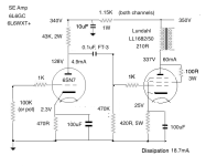
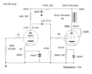
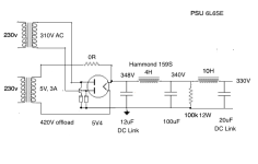
This is a useful thread! I liked the combination of 6SN7 and 6L6 so much that i modified another of my amps to use this circuit.
Sovtek 6L6WXT+ is the best sounding output in triode of those I have, followed by 6L6GC. Both were better than coin base 6L6WGC or various EL34s.
I like the angled plate 6SN7s best. The rectifier was a GE 5U4GB. All the tube choices made a difference.
Coupling caps are teflon FT-3. Cathode bypasses DC Link.

My amplifier will be wired for pentode operation and will use EL34 since that's what I have,
- Home
- Amplifiers
- Tubes / Valves
- 6SN7 + EL34 SE stereo amplifier build - questions

