I wonder what the effect of inserting an Ixys 10M45 or 10M90 constant current diode in the g2 connection, fed from the HT not the anode?
It wouldn't work I expect because the grids require voltage rather than current.
Alternatively, you could use one to produce a stable voltage for the grid by using it like a Zener diode in series with a resistor from the HT. (would need to be heatsinked)
No way is 26ma flowing through the grids of an EL34 or similar unless you have four of them.
It is not idle current. When the anode voltage goes down g2 current goes up quite a bit, especially in pentode mode where the anode voltage can go significantly lower than g2.No way is 26ma flowing through the grids of an EL34 or similar unless you have four of them.

I'm a bit late to this party and I haven't read all the thread, just part of it. I can see the starting point - a 2 stage SE amp with resistor loaded 6SN7.
I've been curious about the EL34 in triode so rigged up an output stage today and tried it out with a pair of Japanese 3.5K OPTs. Schematic below. I drove it with my 10Y DHT stage, and got some good sounds. Not quite loud enough, but plenty of quality. I found it nice - better than expected. Well balanced, good voices, good though not great piano, well defined bass. It's quite a light and clean sound, very easy to listen to through my Tomiko OPTs. They seem to match up well. I'm not getting any frissons, but well pleased with this experiment. The sound should get better. I've used not my regular DC Link cathode bypasses but my "alternative" cathode bypasses, namely Elna Silmic 2 and Audio Note Kaisei in parallel. 47uF plus 50uF = 100uF. The Silmics need a few days to open up - they start a little shut in but improve. There are a lot of SE EL34 designs and it's well thought of in triode. The volume is down so I can't do listening assessments at my normal volume. Just about enough to enjoy the music. Gain should be 10.5. All this through my revised and tweaked 10Y stage. If I wanted more volume I'd use a 27/37/56/76 to drive it - I like these 5 pin tubes.
So I'll add my voice to those who like EL34 in triode. It's nice and well worth building with.
This project is not dead and neither am I! 🙂
Life took me on a year-long detour, and I am finally getting back to this amplifier and also a different one that I am building. Better output transformers for this one arrived from AliExpress today. They are about twice as big as the ones that came with the kit. Anyone not familiar with my kit purchase mistake - different versions of this kit come with different OPTs. I made a mistake when I checked out from my shopping cart and bought the kit with the smaller ones. I now have the larger ones that I intended to buy. Other parts are being added to my Mouser and DigiKey carts for both projects right now.
Life took me on a year-long detour, and I am finally getting back to this amplifier and also a different one that I am building. Better output transformers for this one arrived from AliExpress today. They are about twice as big as the ones that came with the kit. Anyone not familiar with my kit purchase mistake - different versions of this kit come with different OPTs. I made a mistake when I checked out from my shopping cart and bought the kit with the smaller ones. I now have the larger ones that I intended to buy. Other parts are being added to my Mouser and DigiKey carts for both projects right now.
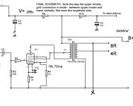
Proposed schematic attached. Comments welcome. Several people have said, "It ought to work" but who knows until I try it and see what actually happens. Really this is just an experiment, so I will not be enormously disappointed if it doesn't work out well. Maybe I'll be surprised. Single-ended pentode with regulated screen voltage.
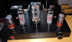
The project as it stands now, before the chassis gets painted black:

The regulated screen supply (since this is a pentode amp) PCB and most of its components are a "free" donation from another China amp kit project, and the cap can is one I had on hand that can be restuffed with three 120uF filter caps like I did with another kit build.


The project as it stands now, before the chassis gets painted black:
The regulated screen supply (since this is a pentode amp) PCB and most of its components are a "free" donation from another China amp kit project, and the cap can is one I had on hand that can be restuffed with three 120uF filter caps like I did with another kit build.
Last edited:
You might be interested in moving the feedback takeoff point to the primary of the OPT. This greatly improves the peformance of the OPT for both low frequency response due to primary inductance and its dominant 3rd order distortion, at some expense in the leakage inductance losses at high frequencies (now uncorrected by feedback) and some extra effort to bias the driving stage. Another advantage is much greater stability margin.
The feedback resistor scales up with signal voltage, so with turns ratio. Since it adds DC current across the driving stages' cathode resistor, this must be juggled to keep both bias and feedback where you want them, but that's not rocket surgery. You will possibly be able to remove C1, C2 // R5, R6.
All good fortune,
Chris
ps: C5, C6 are very large, unnecessarily increasing overload recovery time and decreasing LF stability margin. These should determine the first dominant pole.
C5, C6 are very large, unnecessarily increasing overload recovery time and decreasing LF stability margin. These should determine the first dominant pole.
I honestly do not remember how I arrived at that 0.33uF value. The original schematic, which was a very different animal using two parallelled triode drivers, used 0.1uF in those locations. What would you recommend?
And explanations are always welcome as I am not an expert by any means. Much of this is a learn-as-you go experiment for me. I look at the 6SL7 graph that I drew, and I can't believe that I actually did that. Fortunately, I wrote down exactly how I did it in case I ever need to do it again because I will never remember.
A question also has arisen on whether I should reduce the value of the first cap in the 120-120-120uF in the power supply. The durability and heat generation of the Chinese power transformer is questionable. I have already reduced the load on it somewhat by removing the 5.9V required by the rectifier tube that I will not be using, and I'll also be heating only three tubes instead of four.
Two issues with the value of the coupling capacitor. First is setting a fixed (signal level invarient) first pole. The output valve source resistance // reflected load resistance x primary (magnetizing) inductance forms a LF pole that varies with signal level, moving lower with increasing signal. This cannot be used as the dominant pole because it approaches the RC pole across the coupling cap. Two overlaid poles make an oscillator.
Second issue is overload recovery time. Clipping occurs at the output valves' grid, where it conducts on peaks more positive than zero bias, and the diode conduction charges the coupling cap, changing output valve bias, which bleeds back down at the rate of RC. For best quality OPTs this RC dominant pole can be located at about 1/4 second = 4hz. For an unknown and SE transformer with likely fairly small primary inductance might want to move this up an octave or more.
Heating of the power transformer may not change noticably with first cap values, within reason, but radiation from the spike intensity will. In either case, you might consider a snubbing network across the transformer's secondary winding. Even a crude guess, like 1000 Ohms in series with 1000pF or 2000pF, would help. Mount it as close as possible to the windings, one snubber per half winding.
All good fortune,
Chris
My notes from a while back reference some spreadsheet that I can't find now. Maybe there was an error on it when I calculated 0.33uF? Who knows. So how about this:
0.33uF
=1/(2*PI*(anode output impedence Ohms + grid leak Ohms)*(coupling cap uF/1000000))
=1/(2*3.14(44000 + 330000)*.33/1000000))
=1/(2*3.14(374000)*0.00000033))
=1/.7750776
=1.29Hz
0.22uF
=1/(2*PI*(anode output impedence Ohms + grid leak Ohms)*(coupling cap uF/1000000))
=1/(2*3.14(44000 + 330000)*.22/1000000))
=1/(2*3.14(374000)*0.00000022))
=1/0.5167184
=1.94Hz
0.1uF
=1/(2*PI*(anode output impedence Ohms + grid leak Ohms)*(coupling cap uF/1000000))
=1/(2*3.14(44000 + 330000)*.1/1000000))
=1/(2*3.14(374000)*0.0000001))
=1/0.234872
=4.26Hz
We typically aim for something around 2Hz, which would indicate 0.22uF for my C5 and C6 coupling caps, correct? Or am I misunderstanding and/or miscalculating here?
Your numbers look right, although exactly speaking driver anode output impedance appears in parallel with its plate load resistor - not important of course.
The choice of frequency of dominant pole will vary with the frequency of the other LF pole, so with the OPT primary inductance and its associated circuit resistances. Pentode operation is worst case, but not by as much as one might think - the load's reflected impedance is in parallel with plate resistance.
What we want is a frequency far enough above the output LR pole as to "dominate" the phase vs. frequency curve, the further the better for this criterion. But not so high as to overly impact the final amp's LF response. How to choose? If we knew the OPT's primary inductance at small signal, with actual DC current passing through it, we could easily calculate the output RL pole, and we know that that pole moves away from the higher frequency dominant (RC) pole with increasing signal, thus stable with signal. We would put our RC pole an octave or two higher, maybe more, and declare victory.
Without measuring the inductance, we could make a guess and add some conservative margin for guessing error. I'd personally start around 16Hz for the dominant pole, although you may be stable enough at as low as 8Hz, or would have faster overload recovery (and higher stability margin) with 32Hz. Just guessing numbers of course.
All good fortune,
Chris
OPT supposedly rated at:
Inductance: L>=26H (test frequency is 100HZ);
Primary DC resistance: <360ohm
Is that what we need?
A guy who gutted and redeisgned one of the many variations of these kits found that the transformers went down to 8Hz at 1 watt. I have the same OPTs except that I ordered them without UL taps.
Timestamped:
He used 0.22uF 630V coupling and 470k grid leak. I have drawn in 330k grid leak, and I have no idea why I chose that value a year or so ago.
His creative approach:

I considered copying his design but what fun would that be? 😀 😀 😀 😀 😀 I also wasn't thrilled with the three 6SN7 tubes required.
Inductance: L>=26H (test frequency is 100HZ);
Primary DC resistance: <360ohm
Is that what we need?
A guy who gutted and redeisgned one of the many variations of these kits found that the transformers went down to 8Hz at 1 watt. I have the same OPTs except that I ordered them without UL taps.
Timestamped:
He used 0.22uF 630V coupling and 470k grid leak. I have drawn in 330k grid leak, and I have no idea why I chose that value a year or so ago.
His creative approach:
I considered copying his design but what fun would that be? 😀 😀 😀 😀 😀 I also wasn't thrilled with the three 6SN7 tubes required.
Last edited:
Inductance in iron core transformers varies with test voltage, DC current, and frequency, so numbers without all three aren't IMO even numbers, just aspirations. But you could cook up a pole frequency using the supplied number and add whatever safety margin you feel to be appropriate. The pole is where X-sub-L equals the parallel of impedances feeding it, so the parallel of output valve "plate resistance" with reflected load impedance, for which we would take the transformer's rated load impedance, a coupla K Ohms.
X-sub-L varies linearly with frequency, so it's easy to extract frequency (21.4 Hz with 3K5 parallel R), slightly harder to believe it. One good thing is that SE amplifiers bias the OPT's curve up into a small signal region pretty linear with signal, so there are fewer surprises and the amount of DC present is less critical than in a push-pull. 26 Hy seems, to me and just an opinion, on the high side of possible if measured with DC and small signal, but possible. Giving yourself an extra octave of margin sounds either conservative enough or too conservative, but in that range.
All good fortune,
Chris
Last edited:
Ok, so we don't really have enough info it seems. In that case, it seems like I should try 0.22uF and see what happens but also have 0.1uF on hand just in case I need to swap them out. That's easy enough. Original schematic was 0.1uF and 220k, but that design used 6SN7 driver tubes with the triodes wired in parallel. I have some more math to do ...
Last edited:
I have some more math to do ...
Looking back at the original schematic with the 6SN7 drivers with their triodes in parallel and 220k resistors, it looks like they targeted 7-8Hz. So let's look at 8Hz and my 6SL7 single driver:
6SL7
=1/(2*PI*(anode output impedence Ohms + grid leak Ohms)*(coupling cap uF/1000000))
=1/(2*3.14(44000 + 330000)*.05/1000000))
=1/(2*3.14(374000)*0.00000005))
=1/0.117436
=8.5Hz
So, 0.05uF with that math.
Hmmmmmmm ... adding to shopping cart 0.22uF, 0.1uF, and 0.05uF. They are cheap enough. I'll start with 0.1uF and see what happens.
In any case, it appears that 0.33uF was in fact way too big, so thanks for catching that. 👍
8.5Hz is of course below the LR pole at the output using given values. For an SE amplifier, with its greater OPT immunity to signal level variation of primary inductance, you can make the LR pole at the OPT our dominant pole, and without a feedback loop this is the usual case in modern DIY SE designs. The poorer overload recovery is accepted as given, and unimportant for many folk. "Just turn it down."
All good fortune,
Chris
All good fortune,
Chris
Thus my aiming blindfolded at a dart board and hitting 0.1uF as my starting point, unless you see something I don't that would tell me it's a really bad idea to start there. We don't really have enough info, but I have to start somewhere.
You'll be fine. Don't let my quibbling slow down your building. I'm just an old kvetch.
All good fortune,
Chris
All good fortune,
Chris
Your return has inspired me to revisit my Chinese EL34 SE amp. I bought a pair of sensitive speakers (90db) - Triangle Borea BR03 to use with it.
I've removed the 6SN7s and associated components and use an Akido Noval as the VAS in a separate chassis. There is no overall feedback.
I have the original PSvane EL34s and also an unsued pair of JJ/Tesla KT77s.
I blundered with the Akido switchable output caps - 2.2uf and 0.1 PIO so based on recent replies I need to swapp the 2.2s for 0.22s. Ignore the text on the schematic, it refers to the original schematic,
Attachments
@Chris Hornbeck (or anyone else) I know you mentioned the negative feedback earlier. Do you have an idea if I am in the ballpark with the feedback resistor values shown? R19, R20, R7, R8. I'm fine with global negative feedback. These were the values shown on the original schematic (2k and 150R), but that schematic had the paralleled 6SN7 drivers and I have now changed to 1/2 6SL7 instead. I can't find any simple guidelines for NFB online. I did find a rule of thumb for adding NFB caps, but I can't vouch for its accuracy:
2000/2 = 1000pF = .001uF = 1nF
I wonder if there is an AI algorithm capable of designing a tube amp yet?
I have changed the coupling caps to 0.1uF as discussed earlier.

The feedback cap must be found by trial and error. However, a good place to start is often:
C = 2000/R
Where C is in picofarads and R is the feedback resistor in kiloohms.
If you add too much capacitance, the square wave will round off too much.
2000/2 = 1000pF = .001uF = 1nF
I wonder if there is an AI algorithm capable of designing a tube amp yet?
I have changed the coupling caps to 0.1uF as discussed earlier.
- Home
- Amplifiers
- Tubes / Valves
- 6SN7 + EL34 SE stereo amplifier build - questions