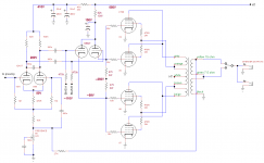
Your original amp picture, post # 18, seems to be a single pair (not parallel) push pull amp with KT90 or EL34, and EL84 drivers.
That is a long way from parallel KT88s (4 per channel), and 12AX7s.
Probably better to have started from scratch.
That is a long way from parallel KT88s (4 per channel), and 12AX7s.
Probably better to have started from scratch.
Seems doable.Supply a bit high for UL and drive voltage from the 12AX7 is barely enough, so the hole thing is on (over) the edge 😱.
You need a neg supply 250V 6mA .And a pos 150V evt obtainable from the +B with a single resistor, sum of the anode currents is constant.
Mona
You need a neg supply 250V 6mA .And a pos 150V evt obtainable from the +B with a single resistor, sum of the anode currents is constant.
Mona
Attachments
Wow! Thanks Ketje.
So, You suggest a buffer than a voltage amplifier instead.
My mind was to use some more like 12bh7 (it seems have little better excursion), for instance in common cathode mode , with a 33k on the plates as voltage amplifier. But what do I know...? I.m not able to design a working functional circuit. Thanks
Last edited:
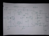
Probably yes, you coupling caps are a bit small, would double them.Think something more like this:
It will work, please ?
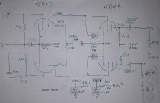
Here an other way.
For the 1mA first stage 100k with -100V, just an example.If you have -150V use 150k.
The diodes are only for protection at start-up.After that they are blocked as if they aren't there.
Mona
Attachments
Last edited:
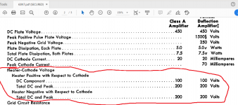
A remaining issue is operating an oxide cathode valve at 600VDC or North of that. You must have a compelling artistic reason to do that, because there isn't an engineering one. WTF?
Just my personal opinion,
Chris
Just my personal opinion,
Chris
I don't think the valve will see 600V ever. More 500 DC + AC for absolute swing , zero current, and usually no more than max 350V dc +pk...No good ?
Last edited:
There are some contemporary valves, Russian production has the best reputation, that run reliably at 500 to 600 VDC. It's likely that we're living at the very tail end of that era.
It's not that the Secret Sauce formula gets lost, it's more like the old guys ( actually, almost always, the old girls) age out and disperse, and the ancient machinery wears and can't be replaced without the ancient demand, so entropy.
In the year 2020 we need to reflect on the past and anticipate the future, where the desire to reverse entropy grows ever stronger. Ain't happenin.
god bless us, every one,
Chris
It's not that the Secret Sauce formula gets lost, it's more like the old guys ( actually, almost always, the old girls) age out and disperse, and the ancient machinery wears and can't be replaced without the ancient demand, so entropy.
Hi Chris,
I consider myself privileged to use this site and have the benefit of the wisdom of the 'old guard'.
All too often those pearls of wisdom are just tethering a concept to a more realistic, achievable goal.
Thank you all!
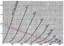
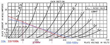
From GE 12BH7 A I noticed from characteristic and typical operations in respect with class A amplifier each section : plate voltage 250V , grid voltage : -10.5V, plate current : 11.5 mA.
Don't think is possible to track a line through that point with a decent load for a supply voltage less than 500V
Don't think is possible to track a line through that point with a decent load for a supply voltage less than 500V
Glancing at the schematic on the previous page I would direct couple the input and driver stages, replace the 490R "tail" on the driver LTP with a far stiffer cascode MOSFET CCS and replace the driver stage plate resistors with a CT plate choke. The choke can swing higher than the B+ and doesn't dissipate voltage like a resistor.
What is the absolute max peak voltage for 12bh7 please ? I read in a th notice could be till 1500v positive peak ? !!! That means it will not be a problem supplied at 600v as time the dc plate voltage will stay within 300v dc around and get full signal swing ?
GE data gives 1500Vpeak as the absolute maximum.What is the absolute max peak voltage for 12bh7 please ? I read in a th notice could be till 1500v positive peak ? !!! That means it will not be a problem supplied at 600v as time the dc plate voltage will stay within 300v dc around and get full signal swing ?
Mona
GE data gives 1500Vpeak as the absolute maximum.
Mona
So will not be any problem to supply at 600v resistor loaded as time the dc plate voltage will be fixed within 300v dc ? Am I wrong please ? The operation point will be fixed at 250v around and it will swing positive till 400v dc + ac. Supplied at 600v will give the possibility to get 100v rms output which is fine.What is wrong with that I try to understand, please?Thanks
Last edited:
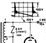
According to GE the tube is ment to be used in an vertical deflection output stage.There you get signals like thisSo will not be any problem to supply at 600v resistor loaded as time the dc plate voltage will be fixed within 300v dc ? Am I wrong please ? The operation point will be fixed at 250v around and it will swing positive till 400v dc + ac. Supplied at 600v will give the possibility to get 100v rms output which is fine.What is wrong with that I try to understand, please?Thanks
So, for your application i see no problem.
Mona
Attachments
Interesting stuff, I'm mucking about with quad of 807's UL PP AB1 at present, which as suggested previously takes some driving, I've been pondering direct coupling, so some questions that might help the OP and clear up a few queries for myself.
I've been using Russian 6H8C's and have searched for an octal 12BH7A equivalent but never found a suitable candidate, is there one?.
Williamson type amps used a dedicated 6SN7 common cathode gain stage driver instead of a KF. Which approach is better? I've read various threads disparaging cathode followers but never really found a reason why.
If RC coupling is used say for a paralleled OP stage is it better to use two coupling caps as per normal or one coupling cap per valve?
Lastly for difficult driver stages such as this which is better on the whole, valve KF or Mosfet Source follower?
All of these extra stages obviously increase the chances of instability another aspect that needs bearing in mind.
Andy.
Last edited:
- Home
- Amplifiers
- Tubes / Valves
- 6sn7 driver question