Hi All,
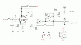
I have a cheap 6SN7 based tube buffer as the attachment but the mid/low area sounds quite muffled and the highs are not extended enough to my taste as well. Also during the playback of some loud passages, it could sound compressed and somewhat distorted.
I can see C24 and C34 are WIMA black box caps and C26 and the other paralleled caps are WIMA MKS4 and Philips MKT. I don't know much about electronics but can a simple tweak like replacing the C26 C24 C34 to some audio grade capacitors improve the sound quality?
Thanks!
P. Sugano
Attachments
What are the ( resistor) component values like and what voltage do you have at the plate ?
C29 at the input will cut HF . What value do you have and the resistors with it ?
Do you need the extra gain that you get with parallel triode use. If not then a single half might give better sound. With 240 volts at the supply , you should get clean sound.
The 6SN7 is a good tube.
The resistor values will help a lot in giving you some suggestions.
Cheers.
Muffled, huh? And then people tell you paralleled sections sound just as good but with half the output impedance.
If you are reluctant to undertake such an extensive surgery upgrading the black boxes will still bring some improvement. There is no need for the input cap assuming you use quality sources with no or low dc.
If you are reluctant to undertake such an extensive surgery upgrading the black boxes will still bring some improvement. There is no need for the input cap assuming you use quality sources with no or low dc.
Your main problem with this circuit is a high source impedance. Even with paralleled sections, the 6SN7 is not a good candidate for this topology. It is probably the best tube out there for a real buffer circuit, but this circuit isn't one.
If you were to redesign, unparallel the sections, use the first as a common-cathode amp, then the second as a cathode follower.
If you were to redesign, unparallel the sections, use the first as a common-cathode amp, then the second as a cathode follower.
I agree with Stuart.
The 6SN7 has plate impedance around 7K; so a T-barred bottle will give 3.5K in parallel with the plate load (which should also take account of the AC load on the cold side of the output cap.)
Ergo, with maybe a plate load of 3rp, say 10k, you'd have a Zout of no less than 2.6K. With the wrong interconnects and/or a low Z amp, this could sound rather indistinct, agree, but this might also be exacerbated by sag in the B+ supply.
There is an attempt in the circuit to trade gain for lower Zout, by use of the resistive divider, but this may not solve the problem either even though it will decouple the tube plate from the load.
The better option is to direct couple a CF to a plate loaded voltage amplifier as per Stuart's suggestion.
Some subtlety is necessary here, too. Choose around 22K plate load (giving you, with a cathode bypass cap, an Av around 75% of mu, or 14), then use 25K as the CF tail resistor. This will mean that as the VA draws more current, the CF draws less, but in a slight imbalance which will promote some H2/H3, or sweetness. A gain of 14 is far more than you need, in which case you should first delete the cathode bypass cap on the voltage amp, then perhaps further attenuate the input to the voltage amp with a simple resistive divider. Zout at the CF should be around 200R, though it is asymmetrical, but this should not cause problems.
You should run around 7.5mA in the first section, which mandates a supply of at least 300V, and perhaps even 320V.
As you can see, this is a very different design configuration, but it will sound much better and enable use of the same tube.
Cheers,
Hugh
Hugh, it's even worse than you make it out to be. Quantifying the source impedance is impossible without circuit values, but the unbypassed cathode resistor guarantees that the source impedance will be higher than 7K.
To add insult to injury, the B+ is mighty low for this tube. A 6SN7 wants to see minimum 180V on the plate.
To add insult to injury, the B+ is mighty low for this tube. A 6SN7 wants to see minimum 180V on the plate.
Loading for a tube
Hi Dr. Hattori,
I am wondering what are effects when this circuit is connected to a extremely low impedance loading of few kilo ohms.
Johnny
Hi Dr. Hattori,
I am wondering what are effects when this circuit is connected to a extremely low impedance loading of few kilo ohms.
Johnny
Thanks everybody for all the ideas and inputs.
So I guess simple tweaks=higher grade components alone won't improve the sound much but a completely different circuit topology is needed.... Seems like I have a very long way to go.
So I guess simple tweaks=higher grade components alone won't improve the sound much but a completely different circuit topology is needed.... Seems like I have a very long way to go.
I built a simple 6sn7 base preamp from some ideas on Audio Asylum. Here is a link to my post. In that link is a link to the original post. I couldn't find the schematic but I should have it somehere but the post should help you.
It uses 1/2 a 6sn7 for each channel.
http://db.audioasylum.com/cgi/m.mpl?forum=tubediy&n=71630
I did find the author's web page and he shows a 12az7 based pre:
http://www.joeltunnah.com/buffer.html
rick
It uses 1/2 a 6sn7 for each channel.
http://db.audioasylum.com/cgi/m.mpl?forum=tubediy&n=71630
I did find the author's web page and he shows a 12az7 based pre:
http://www.joeltunnah.com/buffer.html
rick
Originally posted by AKSA
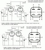
The better option is to direct couple a CF to a plate loaded voltage amplifier as per Stuart's suggestion.
Here are a couple variations Frank posted some time ago.
dave
Attachments
Thanks for the pre amp circuits!
As the original buffer is fed by the output of a PCM2702 USB DAC, how do I replace the old buffer with the circuits you uploaded? I know these are preamp circuits so the volume pot has to go but to make the new circuit work with the pcm2702 output, what change do I have to make precisely?
Thank you
As the original buffer is fed by the output of a PCM2702 USB DAC, how do I replace the old buffer with the circuits you uploaded? I know these are preamp circuits so the volume pot has to go but to make the new circuit work with the pcm2702 output, what change do I have to make precisely?
Thank you
Hi sugano,
if I understand the cir in your post #1 is not a buffer.
It, at first, amplifies voltage and then reduces it by means
of r12, r29 partition.
In this way you have little noise but great distortion.
I'll go with a cathode follower.
bye
federico
if I understand the cir in your post #1 is not a buffer.
It, at first, amplifies voltage and then reduces it by means
of r12, r29 partition.
In this way you have little noise but great distortion.
I'll go with a cathode follower.
bye
federico
planet10 said:
Here are a couple variations Frank posted some time ago.
dave
Hi Dave,
Thanks for uploading Frank's preamp circuit. Now what do I need to do to connect this circuit to the output of a PCM2702? It is going to be a USB DAC so I don't need a volume pot but what else do I need to do to make it work? Someone please help.
Peter
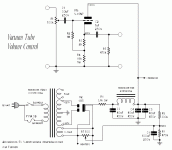
The power supply would have big impact on the sound quality as well. Therefore, we shall pay more attention to it.
Some experts say a simple power supply with tube rectifier, LCLC filtering would be good for the line amp.
Johnny
Some experts say a simple power supply with tube rectifier, LCLC filtering would be good for the line amp.
Johnny
- Status
- Not open for further replies.
- Home
- Amplifiers
- Tubes / Valves
- 6SN7 based tube buffer


