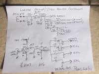
Here is my design for a linestage preamp I have been using for a couple years now, and I quite like it.
With 4 sets outputs, you can run a set of speakers with a level control for different drivers. Amplifiers can be had cheaply! 6SN7 as the amplifier, AC coupled to a 6V6, but taking the signal from the cathode. From that point, there are 4 x 10K dual log pots connected in parallel. Coupling cap sizes can be chosen to give a -3db HP filter of whatever you want, in this case I have 2 sets for about >80hz and the other 2>18hz.
I would be happy to hear any criticism. Maybe using a CCS source somewhere to have a real stable DC rail at the 6V6 cathodes (not sure if there is an issue there).
Can I get away with 4 x 5K dual pots in parallel? ie what is lowest impedance the 6V6 can deal with? 4 x 5k =1.25k 5VRMS/1250 = 4ma. Square that then multiply by 1250 = miniscule wattage output (.02W)
Anyway, it is something a little different I do think it sounds quite good.
Attachments

Your filter/crossover design will be very output impedance dependant the high pass filter frec will vary when changing output load (would need very light loading) it would be better using the output buffers after the coupling caps/filters but would require several tubes more.
I would use only a adjustable high pass/low pass stage using the 6v6 tube directly at output as a real line buffer (or another smaller tube the 6v6 is an overkill for that application) using more tube count (one extra "triode" per output)
but would use lots more parts and would require to do more holes for the tubes
Last edited:
Sorry have a lapsus with your post I now see you only want a high pass to remove de LFO from 80hz and below, and a couple outputs for diy.... 😀
In your schematic are you sure the 6v6 is connected like that? your 6v6 would be passing tons of current (almost 0V cathode bias through 470 ohms with 340V on plate).

In your schematic are you sure the 6v6 is connected like that? your 6v6 would be passing tons of current (almost 0V cathode bias through 470 ohms with 340V on plate).
The schematic is correct. 342VDC at the plate. 20.1VDC at the cathode. Not sure about the first post. Perhaps you can explain? The parallel portion of the 10k pot is the dominating figure in output Z. If the pot is used in the neighbourhood of noon the 2k output Z. That has not caused any issues. There would have to be a boatload of cable capacitance after that point for the LP filter created by RC network.
But I am interested in hearing about using lower valued pots. Maybe even 3 x 2k, one full range output, 2 others with higher -3db points.
But I am interested in hearing about using lower valued pots. Maybe even 3 x 2k, one full range output, 2 others with higher -3db points.
Sorry in my first post I quickly read your post and thought you were trying to design a tube based crossover....... so ditch the first post 😀
the problem with your design is that you are using the output tube (6v6) like a pentode in a horribly linear part, it will pass audio but is using the tube beyond the recommended for a follower duty.
Here you can see an approximate loadline for the circuit using Rk=470 ohms.

In that fashion the loadline is super steep and will generate lots of thd if you change some simple things you can increase the output capability in minimize the thd without burdening lots of power through the tube.
the problem with your design is that you are using the output tube (6v6) like a pentode in a horribly linear part, it will pass audio but is using the tube beyond the recommended for a follower duty.
Here you can see an approximate loadline for the circuit using Rk=470 ohms.
In that fashion the loadline is super steep and will generate lots of thd if you change some simple things you can increase the output capability in minimize the thd without burdening lots of power through the tube.
So with 342VDC at the anode, what value of Rk are you suggesting. Actually, I might have made a mistake - I might have meant to connect them as triodes, but I wasn't sure what difference that would make.
Here is a quick graph some may say it is also a bit rude for cathode follower but it will work a bit better 😀

With your proposed setup it seems it could drive a much lower external load as that load is in parallel with the Rk1 which is approx 100 ohms. I will try that site and see what I can come up with. I am not fixed on using a 6V6. EL84's are possibility, but am open to ideas.
No RK is the sum of Rk1+Rk2 so in fact the output impedance will be RK||RI (RI: triode RP) it will be in the vecinity of 1800 ohms at ~30mA with a trioded 6v6 if my memory doesnt fails me.😛
Sorry another lapsus the past Zo is only valid for anode follower In a cathode follower Zo~1/gm so for a 6v6 it is ~200 ohms
Sorry another lapsus the past Zo is only valid for anode follower In a cathode follower Zo~1/gm so for a 6v6 it is ~200 ohms
Last edited:
- Home
- Amplifiers
- Tubes / Valves
- 6SN7+6V6CF Linestage Pre