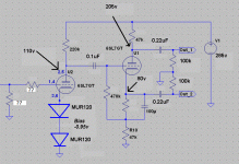
I recently removed the volume pot on my push pull amp in favour of a bit-perfect digital volume control.
After removing it, I've realised I will need to ground the input stage and also put a grid stopper (which was missing). I've seen values of 100k up to 1M for the input grounding, and also values of between 220R and 1k for the grid stopper.
What values will minimise noise/RFI?
After removing it, I've realised I will need to ground the input stage and also put a grid stopper (which was missing). I've seen values of 100k up to 1M for the input grounding, and also values of between 220R and 1k for the grid stopper.
What values will minimise noise/RFI?
Attachments
I've realised I will need to ground the input stage and also put a grid stopper (which was missing). I've seen values of 100k up to 1M
for the input grounding, and also values of between 220R and 1k for the grid stopper.What values will minimise noise/RFI?
The higher the grid stopper, the better the rfi rejection, but values too high may work with the input stage's Miller effect to roll off the highs.
The resistor to ground will be in parallel with the source impedance, so its value won't usually cause a noise problem.
Since the source will usually have a coupling capacitor, that resistor shouldn't be small enough to cause a loss of bass.
Too high values and an open input may result in bias change due to grid leak.
To add to Rayma's response, going by the datasheets 2.8pF input capacitance, I would say you could go all the way up to 47k for the grid stopper without interfering with the high end response.
Ok - so I'll try a 47k for the grid stopper, and 1M for the grid leak resistor and see how it sounds. I assume 1/2W rated metal film resistors will be ok?
For the most part, low gm types, like the 6SL7, do just fine with a 100 Ω carbon composition grid stopper. Miller capacitance in 6SL7s is high. To avoid exposure to HF roll off, hold the grid to ground resistance down to 100 Kohms.
There is a formula to calculate the gridstop required which is based upon the gm of the tube.
I recall that using that formula for a 12AX7 resulted in a value of 4K7'ish as the minimum value. 6SL7 has a very similar gm to a 12AX7 so I would use the same 4K7 value.
The formula was in either Morgan Jones "Valve Amplifiers" or Merlin Blencowe's "Designing Tube Preamps for Guitar and Bass".
Cheers,
Ian
Much smaller values are effective for preventing oscillation which I presume is the concern here. The gm of the 6SL7 is frankly low enough that in many cases you could get away without it with careful layout. I would minimize the value as the stopper will generate significant and possibly audible noise. I would stick to 1K or less.
Thanks all - I have tested values from 220r through to 10k with no audible changes, so 1k should be fine. At least it has eliminated this as a source of hum!
The amp has a nasty hum which increases if I touch the chassis. I thought it would be linked to rfi. If I turn the amp off, it lingers for a while. Perhaps it is a ground loop as I've tested the heaters with dc, AC and elevated + centre tap resistors!
The amp has a nasty hum which increases if I touch the chassis. I thought it would be linked to rfi. If I turn the amp off, it lingers for a while. Perhaps it is a ground loop as I've tested the heaters with dc, AC and elevated + centre tap resistors!
You forgot to include Miller capacitance?famousmockingbird said:going by the datasheets 2.8pF input capacitance
1k or thereabouts will be fine. Any resistor type will do, as all it is doing is adding some loss to the UHF resonator which we call audio wiring. The 'grid to ground' resistance affects LF rolloff, not HF rolloff.
You forgot to include Miller capacitance
No I didn't, human hearing is to 20kHz correct?
2.8pF is the value for grid to plate capacitance. Multiply 2.8pF by the gain and add the grid to cathode capacitance. I just guestimated the gain of the stage to be 60.
(2.8*60)+3=171
1/(2*3.14*47000*(171*10^-12))=19812
So I was just stating that he probably wouldn't hear a difference all the way up to 47k grid stopper value.
The 'grid to ground' resistance affects LF rolloff, not HF rolloff.
Yes of course.
Last edited:
I assume 1/2W rated metal film resistors will be ok?
If you like the sound of metal film resistors. They will be in series with the signal.
It has been my experience that the smaller the value of grid stopper, the more dynamic the circuit sounds. I always use the smallest value that I can get away with.
1k appears to be working fine so far, but since I removed the volume pot, the circuit is oscillating like crazy, which makes me think that the pot was simply hiding some underlying issues with the circuitry anyway.
All the grounding is done correctly (ie. output xfrmer negative tap is grounded, mains earth is grounded, input rca shield is grounded, circuit board with PSU is grounded, driver stage circuit board is grounded). It's not a star grounding (I intend to fix this later), but I've checked and it's all grounded fine. Heater hum is non existent either.
I thought the grid stopper and grid leak resistors might have something to do with the oscillation....so far no luck.
Yes of course. Metal film resistors give a metallic sheen to the sound. Carbon composition gives a warm glow, like a coal fire. Metal oxide resistors just sound a bit rusty.john_tracy said:If you like the sound of metal film resistors. They will be in series with the signal.
Yes of course. Metal film resistors give a metallic sheen to the sound. Carbon composition gives a warm glow, like a coal fire. Metal oxide resistors just sound a bit rusty.
😀
I've not found that relatively low gm tubes like the 6SL7 really need a grid stopper at all... though it won't hurt anything.
If it were a 6C45pi or 5687 it would be a different story.
Pete
Like capacitors, the best grid stopper is no grid stopper at all; if you can get away with that. My preference is for tantalum oxide. The downside $$$.
Metal oxide resistors just sound a bit rusty.
I find that if you spray them with enough WD-40 the rusty sound goes away🙄
You mean on the gain stage?
To be honest when i built it I followed this circuit:
http://imagizer.imageshack.us/a/img827/589/mrd.gif
I don't recall who or when it was designed. Sounded fine with a 100k pot in front of it. Now without the pot, it oscillates!
To be honest when i built it I followed this circuit:
http://imagizer.imageshack.us/a/img827/589/mrd.gif
I don't recall who or when it was designed. Sounded fine with a 100k pot in front of it. Now without the pot, it oscillates!
That circuit has global feedback, but yours does not, correct?You mean on the gain stage?
To be honest when i built it I followed this circuit:
http://imagizer.imageshack.us/a/img827/589/mrd.gif
I don't recall who or when it was designed. Sounded fine with a 100k pot in front of it. Now without the pot, it oscillates!
- Status
- Not open for further replies.
- Home
- Amplifiers
- Tubes / Valves
- 6SL7 - grid stopper values

