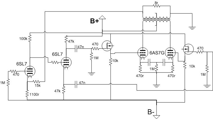
Hello, I was just cobbling together an amplifier based on some ideas I had. For this amplifier design, I have decided on two stacked 150~185V or so each, regulated supplies. Probably going to build a pair of Maida regulators. Do my resistor values seem sane for such an amplifier? I've heard that the 6AS7 can pull grid current and still work very well, so this will be my first amplifier using source followers, in order to prevent loading down my low current splitter on transients, and possibly allowing a smidge more power. Also, for my mosfets, what devices would be good for this application? I've been thinking the DN2540, or IRF820. The way I have them biased seems reasonable, but I am open to suggestions. I know that the 6AS7 can be very mismatched, so I was considering making the FET biasing adjustable, but would like to know the best way to do it reliably. One last thing, would I be better off with the cathode resistors for the 6AS7's going to ground, or should I have them tied together into a current source going to the negative rail?
Attachments
not good myself at the off-the-cuff comments on workability of the values, but...
I'd go with a fixed bias set-up rather than the cathode bias you have. Unless of course you intend to stay COMPLETELY Class A, and you are ok to waste some volts. Since you mention grid current, I'm figuring AB1 or 2, so that means no choice - fixed bias, no option.
THE MOSFET you want is probably the '820s - take a look at Tubelab's Powerdrive for a lead on this set-up.
I don't mind wasting some volts, but whatever works better is what I want to do. I'm possibly going to parallel the output tubes, so I'd like to keep the cathode r's in place for that reason, but would I need separate FETs per output triode? or would the cathode r's be fine for maintaining balance?
Member
Joined 2009
Paid Member
Fixed bias isn't usually recommended for 6AS7.
I made a SET using the 6AS7 output tube with cathode biass and I like the sound very much.
I made a SET using the 6AS7 output tube with cathode biass and I like the sound very much.
I suggest using a current mirror on the cathodes to match the DC current. It's simple and works great in cathode biased amps.
I suggest using a current mirror on the cathodes to match the DC current. It's simple and works great in cathode biased amps.
I'm actually thinking of implementing a Garter bias arrangement, 330r cathode resistors, 165v B+, that means somewhere around 33v across each cathode resistor, which should land me right around 100v, 100mA across each triode, everything I've seen in my experiments points to garter bias as being a very effective reliable means of balance control, even between wildly mismatched triodes. My only real change would be to put the FET between the grid resistor and the triodes' grid. That seems that it would be a great way to maintain balance as well as provide a means of preventing that choke-out that you occasionally get during transients.
- Status
- Not open for further replies.