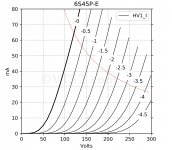
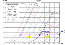
You'd have to run the tube right at 150V with 10mA of plate current (if you run more you could run into some trouble). With all the B+ available for 300B operation, you could probably get away with a plate load resistor. I would make the cathode bias voltage adjustable so you can dial the plate voltage right in (and maybe stretch it to 160V).
Of course santitrucco.
Check out this very old thread on ART forum.
The images are gone, but voluminous text will tell you everything what you need.
AudioRoundTable.com: Group Build >> 300B SE Project, Part 7 - Common cathode 6C45Pi triode driver
Best diying
Check out this very old thread on ART forum.
The images are gone, but voluminous text will tell you everything what you need.
AudioRoundTable.com: Group Build >> 300B SE Project, Part 7 - Common cathode 6C45Pi triode driver
Best diying

Great driver, 150v @ 12 to 15 ma will give best results.
They love to be choke loaded, and respond well with CCS too.
Why so few mA ?
6S45P could work with 200v and 35 mA?
Not to much hours but it can.
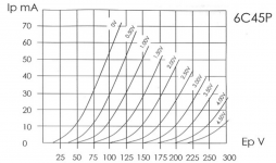
Rod, you're right. Curves are "scattered" at higher voltages for 6S45.
But it's not a problem, the problem is the real oscillation and the very, very hard sound from the 6S45P. Even stop-resistors on each electrode won’t help much.
I personally tried it, and for me (a real fan of the tube sound), anything over 5 mA is too much for 6S45P, IMHO. AC or DC heating, all the same. I very much agree with M.Koster about this tube
Who does not believe, let him try.
Personally, I would believe a lot of what Damir wrote on the ART forum. Damir is a great guy who has seriously tried out about 15 tube drivers for a 300B SE amp.
I know !!!
Last edited:
6C45 is a 'tough nut' for stability, but there are some tough 'nut-cracker' measures that can help in this case:
1. cut off pin 8 as short as you dare, without cracking the glass envelope;
2. remove the contacts of pin 8 from the valve-base;
3. shielded wire for the grid feed to pin 2.
4. grid stopper right on the valve base, but grid leak resistor located 100mm further away (to reduce coupling from the anode node);
5. do not use excessive values of grid stopper. 100-330Ω is enough. We are only trying to spoil the Q of resonant peaks, we are not creating a lowpass filter. Higher values of stopper can make the stability worse, because the anode internal electrode can more easily feed back into a higher impedance node (looking out).
6. With CCS/Gyrator anode load, use anode stopper of 680Ω (for 15mA anode current) 5W wirewound to spoil the Q of the anode circuit resonances.
7. Cathode resistor made of 33Ω unbypassed, plus normal bypassed cathode resistor in series. Unlike the grid pins, the extra cathode pins are helpful, and should all be connected.
8. Special care needed to bypass the anode supply. The capacitors should be mounted near the drain of the CCS FETs: 100µF electrolytic (low impedance type) bypassed with a stacked-construction MKP (TDK B32620A3104xxx series 100nF 250V). Stacked construction is needed to keep the impedance under control up to 10MHz.
The supply capacitor negative should be connected to the cathode bypass cap using 50mm wide copper strip or blank FR4 board.
This decoupling method eliminates inductive parasitics in the anode circuit, and must be good to at least 10MHz, or higher if you decouple further with some SMD C0G MLCCs.
Detecting oscillation to test your work is easy enough - an AM radio tuned to a weak station will be disturbed by a wide range of oscillation bandwidth.
I have a few 6S45P-E, but it's not comparable to trioded D3a/E280F line.
I'm not a fan of this tube (against for example russian 6N30P-DR).
Parameters vary from tube to tube, tendency of oscillation is very strange, the "tone" at larger swing is sharp -even if not oscillating too-, maybe due to the growing H3.
I'm not a fan of this tube (against for example russian 6N30P-DR).
Parameters vary from tube to tube, tendency of oscillation is very strange, the "tone" at larger swing is sharp -even if not oscillating too-, maybe due to the growing H3.
I have a few 6S45P-E, but it's not comparable to trioded D3a/E280F line.
I'm not a fan of this tube (against for example russian 6N30P-DR).
Parameters vary from tube to tube, tendency of oscillation is very strange, the "tone" at larger swing is sharp -even if not oscillating too-, maybe due to the growing H3.
Hi euro21.
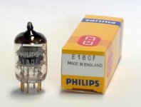
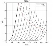
I have some Phillips and Siemens E180F.
And i have using KT in triode mode.
Are they enough to drive ( triode E180F ) the KT88 ?
Santiago.
Attachments
Hi euro21.
I have some Phillips and Siemens E180F.
And i have using KT in triode mode.
Are they enough to drive ( triode E180F ) the KT88 ?
Santiago.
For KT88 in triode? This worked fine for me. I have some nice gold pin Tesla E180F's that are very good... maybe even nicer than the Philips or siemens ones...
However: They are definitely not for driving 300b.
Ian
Be very careful with European variant of E180F.
It is a declared 4W tube in 30mm x 22mm (w/o pins) glass bulb. That is impossible. Trust me, E180F is the most damaging tube in old preamps from broadcast relay stations.
American variants are much more preferred where Pa+Pg2 = 3.3 W in a 36 mm glass bulb (w/o pimple), as shown in RayTheon or Sylvania data sheets for 6688.
As you wish.
Last edited:
Why so few mA ?
6S45P could work with 200v and 35 mA?
Not to much hours but it can.
Just because you can run it those points doesn't make it it sound good there.
I have using these tubes in multiple applications and found that they work and sound great, will drive difficult loads .
Lively, dynamic and detailed.
Just because you can run it those points doesn't make it it sound good there.
I have using these tubes in multiple applications and found that they work and sound great, will drive difficult loads .
Lively, dynamic and detailed.
And which would be a good soun operating point?
- Status
- This old topic is closed. If you want to reopen this topic, contact a moderator using the "Report Post" button.
- Home
- Amplifiers
- Tubes / Valves
- 6s45P 300B Amplifier