I thought that I should share my recent amplifier build:
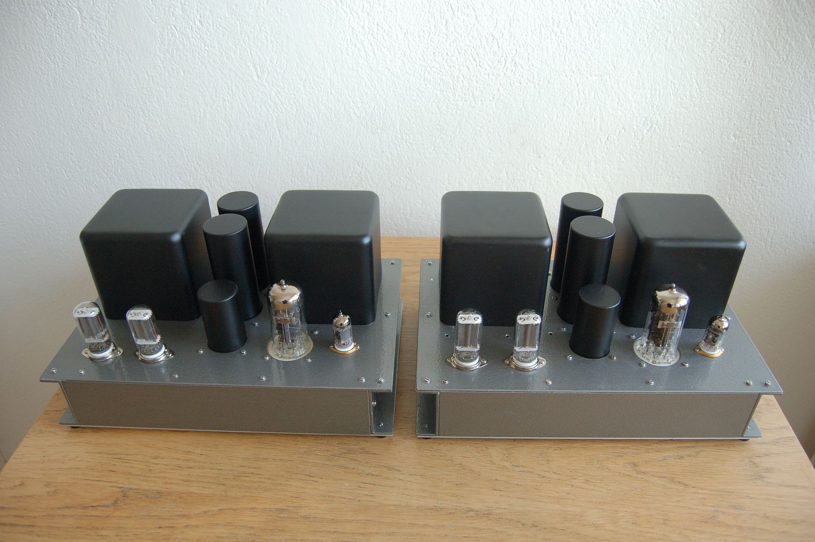
Single-ended 6S41S cathode follower amplifiers that deliver 7 W each. Here is the schematic:
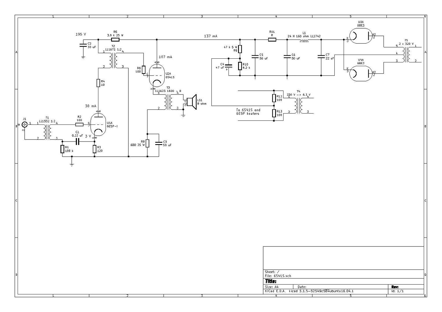
Running the output tube as cathode follower gives a very low output impedance for a single-ended amplifier. These amplifiers can drive difficult loads, but the concept has its cons. The output tubes need over 500 V peak to peak to deliver full output. The driver tube 6E5P-I is a small power tube with high amplification when connected in triode mode. It has a gain around 50 and can deliver quite a bit of current. By using an interstage transformer, I can get the required voltage swing without a very high supply voltage. Also, I step up the signal 1:2 with the interstage transformer and I also step up the signal with 1:2 with the input transformer.
The sound quality is great. It is most certainly the best-sounding amplifier that I have tried with my current speakers.
Single-ended 6S41S cathode follower amplifiers that deliver 7 W each. Here is the schematic:
Running the output tube as cathode follower gives a very low output impedance for a single-ended amplifier. These amplifiers can drive difficult loads, but the concept has its cons. The output tubes need over 500 V peak to peak to deliver full output. The driver tube 6E5P-I is a small power tube with high amplification when connected in triode mode. It has a gain around 50 and can deliver quite a bit of current. By using an interstage transformer, I can get the required voltage swing without a very high supply voltage. Also, I step up the signal 1:2 with the interstage transformer and I also step up the signal with 1:2 with the input transformer.
The sound quality is great. It is most certainly the best-sounding amplifier that I have tried with my current speakers.
Last edited:

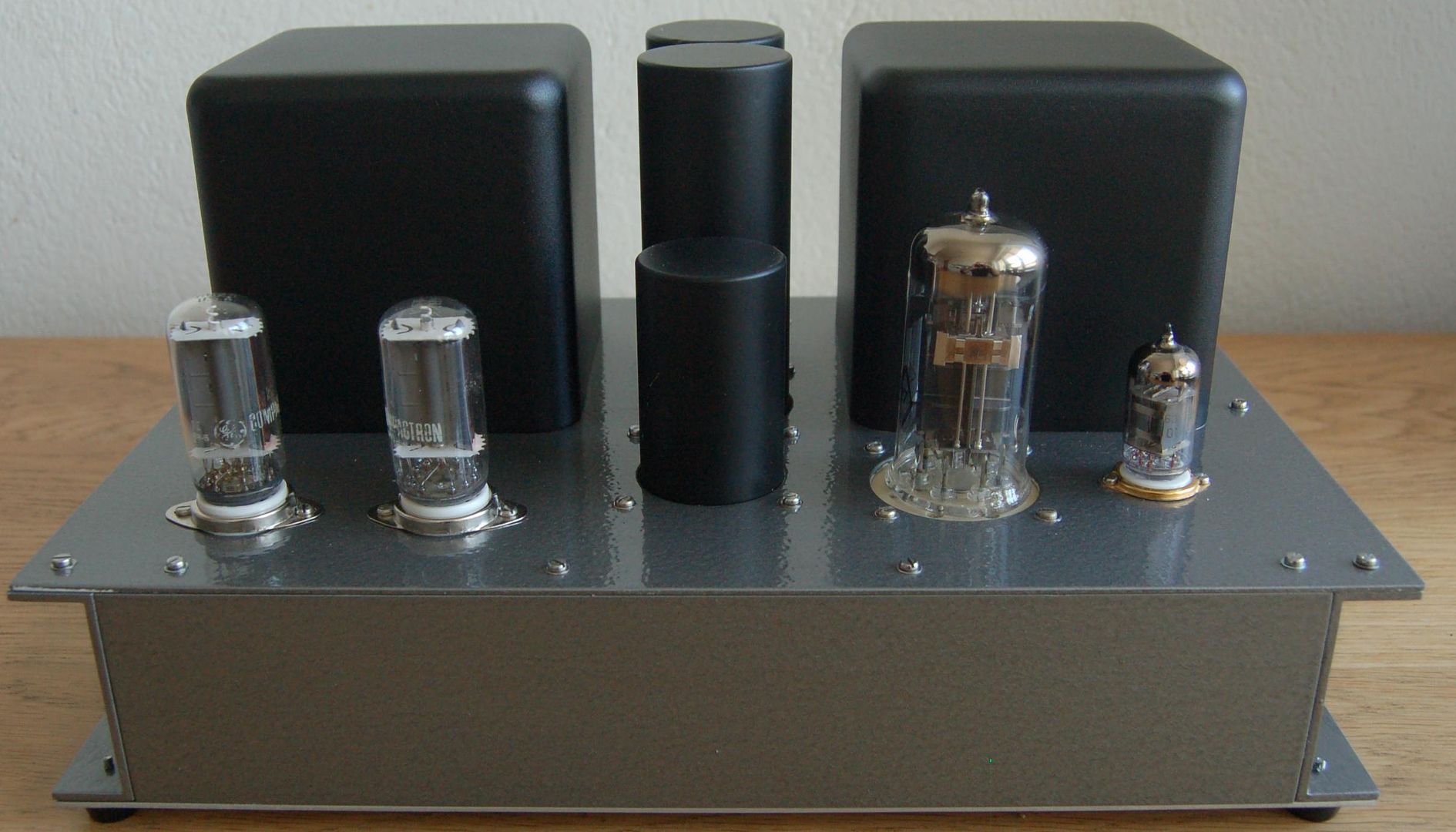
Nice looking chassis work. You build them yourself?
Steve
Thanks! Yes, I followed Morgan Jones' idea in his book "Building Valve Amplifiers" and used aluminium U-profiles.
The driver tube 6E5P-I is a small power tube with high amplification when connected in triode mode. It has a gain around 50 and can deliver quite a bit of current. By using an interstage transformer, I can get the required voltage swing without a very high supply voltage. Also, I step up the signal 1:2 with the interstage transformer and I also step up the signal with 1:2 with the input transformer.
The sound quality is great.
Have you measured the frequency response ?
You have used 6E5P as a triode, but with un-bypassed cathode resistor. This causes the output impedance to raise significantly.
According to Lundahl LL1671 specification (SE to SE Interst. 1:2) the primary inductance is 10 H (only).
http://www.lundahl.se/wp-content/uploads/datasheets/1671.pdf
This combined with your 6E5P stage makes poor bass end frequency response. At 20 Hz the response is -12 dB compared to 1 kHz.
However, if 120 ohms cathode resistor is bypassed with 470 µF capacitor, the response at 20 Hz is only -2 dB.
These results are got with LT Spice simulations.
Last edited:
Arto, I did measure the frequency response. I don't remember the exact figures, but it was flat down to 40 Hz and had a reasonably small drop down to 30 Hz. The cathode resistor is actually bypassed. I am using a method described in Radiotron Designer's Handbook 4th Edition on page 538.
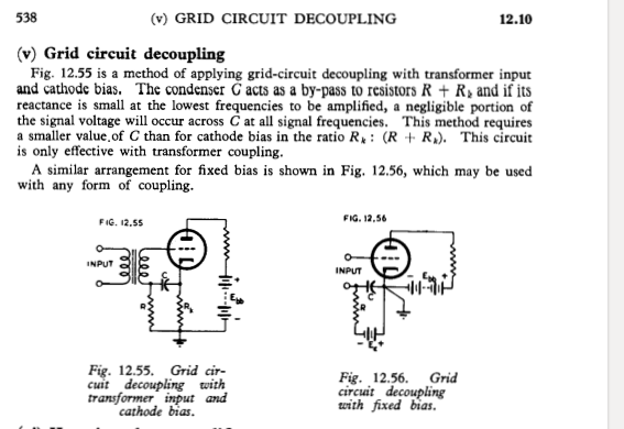
Yes, that really bypass the cathode resistor.
The difference at 20 Hz is some 1...1,5 dB only, compared to conventional bypass method with 470 µF capacitor.
The difference at 20 Hz is some 1...1,5 dB only, compared to conventional bypass method with 470 µF capacitor.
I am not very good at doing simulations and I don't have a model for 6E5P, but I made a try to verify that the cathode bypassing worked before I built the amplifier:
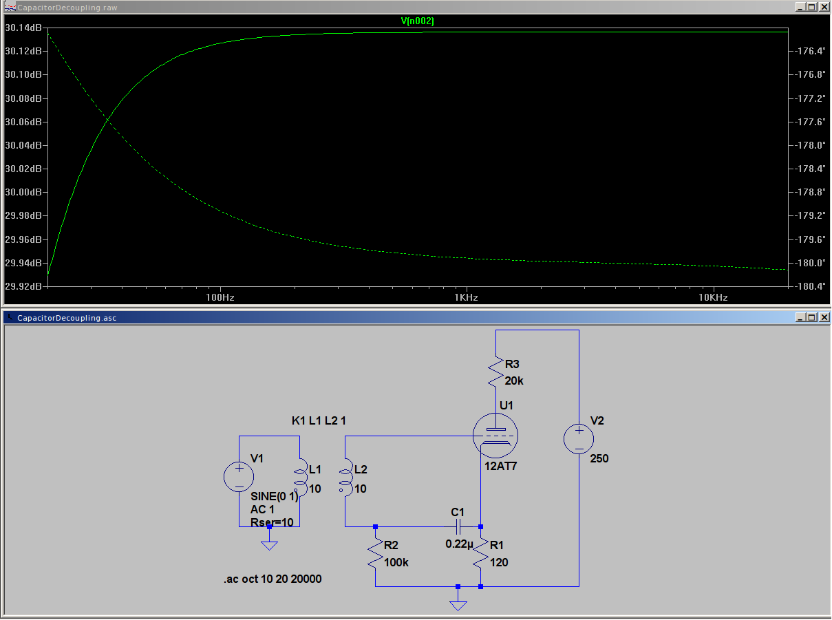
Maybe I am missing something, but it looks like the decoupling is effective?
Maybe I am missing something, but it looks like the decoupling is effective?
To have correct simulation, you should have 10 H inductor at the plate, not a resistor.
20k resistor has no frequency related impedance variation, that is now essential feature.
20k resistor has no frequency related impedance variation, that is now essential feature.
Attachments
Last edited:
Yes, Lundahl's datasheet mentions that the frequency response is +/- 1 dB between 40 Hz and 25 kHz. That also is in line with my measured frequency response. This is a penalty to pay for using the interstage transformer connected this way. But, it does allow me to get away with only two stages and a power supply with fairly moderate tension. My speakers fall off quite rapidly below 40 Hz and I don't perceive the bass response as any poorer than with other amplifiers that I have tried. On the contrary, the bass reproduction is really good - deep and tight.
Arto, leaving the effect of the inductor aside, does the two methods of decoupling the cathode resistor have any impact on the frequency response?
Arto, leaving the effect of the inductor aside, does the two methods of decoupling the cathode resistor have any impact on the frequency response?
Thanks, project posts are my favorite! Lots of ideas come to be remembered with this project... I like the use of aluminum channel for the sides, if one likes the look of wooden sides it would be possible to rip some wood to fit inside the channel and now have the benefit of a totally shielded chassis and a woody, nice! Also I like repurposing TV Compactron damper tubes for tube rectifier, nice slow start and cheap. Also the topology is one not seen that often, hope it sounds good. Also the utter simplicity is great. Nice job dude!
Thanks! It does sound fantastic! 🙂
The damper diodes are really durable rectifiers. I have used them in other amplifiers and they seem to last forever, at least if used with a conservative current.
The damper diodes are really durable rectifiers. I have used them in other amplifiers and they seem to last forever, at least if used with a conservative current.
Your amp and seems very interesting and i think i will build this one too.
Thanks a lot for posting the schematic.
The LL1623 is build in three Versions (60mA, 90mA and 120mA). Which one You are using?
Thanks a lot for posting the schematic.
The LL1623 is build in three Versions (60mA, 90mA and 120mA). Which one You are using?
These sounded so good, I wanted to try the same concept in push-pull. This came out:


Outputs a bit more than 20 W each and sound great!
Outputs a bit more than 20 W each and sound great!
No problems with gassy output tubes? A friend of mine bought a box of 6S41S some years ago and most of them where firecrackers.
I am always puzzled by the low impedance claim of cathode followers.
If the speaker generates a positive current (every other half of a sine, or any other wavefor for that matter), how can the tube dampen that signal?
If the speaker generates a positive current (every other half of a sine, or any other wavefor for that matter), how can the tube dampen that signal?
With the 6S41S that I have tried, no problems.No problems with gassy output tubes? A friend of mine bought a box of 6S41S some years ago and most of them where firecrackers.
Before I settled for using PL519, I experimented with GU-50. Those exhibited pyrotechnics indeed.
- Home
- Amplifiers
- Tubes / Valves
- 6S41S Single-Ended Cathode Follower Amplifier